Tackle Tricky Kettle Reboiler Issues, Part 2
In part one of this series, we started examining exotic kettle-reboiler failures. As promised, we will continue down that path.
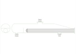
Another less common kettle reboiler problem occurs in kettles or vaporizers with mixtures that have a wide boiling range. Figure 1 includes a kettle reboiler side view of a problem ex-changer. This shows the most common kettle configuration, with the liquid entering directly underneath the exchanger bundle. Operations stated the problem was that the apparent exchanger duty had dropped over the months since the unit started up.
The first thought was that gradual fouling had reduced the exchanger's heat-transfer effectiveness. Fouling is one of the great unsolved problems in heat transfer. While the liquid in the exchanger is not completely stagnant, the liquid velocities are low. Low liquid velocity gives low shear stress at the interface between the liquid and the tube. In turn, low shear stress is clearly linked to high fouling rates in many services. Therefore, the assumption of fouling causing low heat transfer is logical.
Attempts to use anti-fouling and fouling removal additives in the process did not improve the situation. Heat transfer rates continued to drop.
As the problem worsened, samples were taken and checked in a thermal fouling tester (TFT) unit. The TFT unit failed to show any fouling. Careful analysis of the process chemistry and comparisons to ‘similar’ units also showed low or no-fouling operation.
The gradual appearance and steady worsening of this problem showed that the problem must be a small chronic issue that gradually accumulates rather than an acute issue that occurs due to a single, large event.
One interesting problem in condensers is the accumulation of inert gas that gets trapped in a pocket. The inert gas will not condense, making the exchanger area in this pocket unavailable for condensing.
The same type of problem can occur in reboilers. In a reboiler, it is heavy liquid that cannot be vaporized instead of light gas that cannot be condensed. The feed to the reboiler included a small amount of very heavy material with a much higher boiling point (<100°F) — higher than the maximum steam temperature available on the tube side. The liquid velocity on the vaporizing side of the exchanger was low enough that the heavy liquid molecules could accumulate on the shell side. Due to the distance between the exchanger inlet and the tubesheet, a significant pool of insulating liquid of different composition than the regular feed was created. Figure 2 shows the location of the insulated area that had little heat transfer.
What tends to make this problem worse is a combination of more high boiling temperature material in the feed, low velocity in the exchanger, more distance from the inlet nozzle to the tubesheet, and tube support configurations creating isolated liquid pockets. Regretfully, there are no clearly developed guidelines of the combinations of process and mechanical factors that will create an insulating liquid pocket.
If this problem is suspected, the best approach is to move the liquid inlet nozzle much closer to the tubesheet. Another approach is to add an intermittent drain nozzle near the tubesheet to purge the stagnant liquid pool.
Methods to Remove Non-Boiling Liquid
If drain nozzles are not available, several different methods can be used to attempt to remove the pool of non-boiling liquid. All of these requirements will create a deliberate unit upset. The choice between them must be carefully evaluated for your specific situation. Some of these methods may include suddenly dropping the pressure enough to allow flash vaporization in the reboiler to stir up the exchanger. This can cause vaporization in the stagnant area to dissipate.
Second, add a vapor to the reboiler feed line to create a low-density region near the inlet nozzle. This helps the stagnant layer drain away and be mixed with the normal process liquid entering.
Third, isolate the tower from the exchanger and let the stagnant pocket drain out into the inlet line and then purge it from a low-point drain on the inlet piping.
A careful evaluation of the problem system identified the second option as the most reliable of the choices for this case. Unit capacity was reduced. Then inert gas was injected through the low-point drain on the inlet piping to the exchanger. The combination of lower inlet density, high inlet velocity, extra churning of the liquid in the exchanger, and lower partial pressures helped reduce the inlet layer. The inlet gas purge had to be done more than once to be fully successful. Once the stagnant zone was eliminated, exchanger duty returned and full rates were achieved.
While successful, the gas injection is only a temporary solution. A more stable permanent solution was to install a drain valve near the tubesheet.
About the Author
Andrew Sloley, Plant InSites columnist
Contributing Editor
ANDREW SLOLEY is a Chemical Processing Contributing Editor.


