Plant Troubleshooting: When Parallel Paths Create Pressure Problems
Related Reading
- Ponder Parallel Paths
Troubleshooting observations based on parallel paths having the same pressure drop. - Use Your Head with Headers
U-flow versus Z-flow headers in parallel tubing banks. - Mind Equipment Modifications
Maintaining sufficient flow in all parallel paths
I recently visited a plant where a vent-gas handling system required troubleshooting. Complex plants often generate small streams that require treating or disposal.
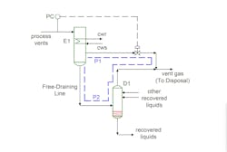
Figure 1 shows the part of the plant system causing problems. Vent gas came from a process unit and entered a condenser (E1). The condenser cooled the gas to recover liquids. The liquids from the exchanger gravity drained through a free-draining system to a liquid recovery drum (D1). The liquid recovery drum (D1) also collected recovered liquids from two other condensers. The non-condensables from condenser E1 vented through a pressure control valve to a common line to a vent-gas disposal system. The common line vent-gas disposal line also connected to the common liquid recovery drum (D1).
The liquid rates from condenser E1 were always low enough that the line from E1 to D1 would always free drain. The line was never sealed. It always had a free liquid surface in the line with a vapor space above it.
This system was not working. The pressure-control-valve vapor line from E1 to the vent-gas control system would go fully closed, and the target pressure on E1 could not be maintained.
This system illustrates one key engineering fundamental for parallel flow systems. The pressure drop through parallel paths must always be the same. This pressure drop balance can combine frictional losses as well as static head. In this case, the parallel flow paths are P1 through the pressure control valve and P2 through the free-draining line, the recovery drum, and up to the point where the two vapor lines combine.
The control-valve action on the P1 line had little impact on the system pressure drop. The vapor flow rates through the two lines would vary, but the overall pressure drop from the E1 feed to the vent-gas line was always low. E1 pressure could not be held. This caused significant operating problems at the upstream vapor vents.
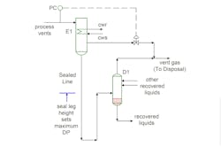
Figure 2 shows a seal leg added to the system. The static head created by the height in the seal leg allows E1 pressure to be higher than the vent-gas system pressure. The maximum pressure difference possible between E1 and the vent system is the height of the static liquid times the liquid density in the seal. Fortunately, this seal leg could be added while the plant was running (due to some valves in the line) and was tall enough to allow for enough pressure drop on the control valve to get E1 up to the desired pressure.
While straightforward, this is a good example of one of the key principles used in troubleshooting parallel flow systems — every parallel path must have the same pressure drop. Understanding this fundamental of flow systems gives every engineer a powerful troubleshooting tool.
About the Author
Andrew Sloley, Plant InSites columnist
Contributing Editor
ANDREW SLOLEY is a Chemical Processing Contributing Editor.


