1660601917729 Variablefrequencydrivests

Optimize Centrifugal Pump System Efficiency

Nov. 25, 2014
Take steps to reduce energy consumption, lower maintenance costs and improve process control

Most chemical plants are working to become more energy efficient. Companies are implementing energy management software, installing occupancy sensors throughout plants to help lower electricity bills, and even changing times of operation to use less power at peak load to avoid the associated higher rates. One of the best ways to save energy is to focus on motor-driven pumps.

Pumps consume more energy in chemical plants than any other category or type of rotating equipment. The average annual spending on pump maintenance and operations is approximately 50% greater than that of any other rotating machine, according to a recent study by the FiveTwelve Group. Companies that operate large numbers of pumps usually recognize the high energy costs as well as the impact pumps have on reliability and process control. However, too many organizations focus on these factors separately when, in fact, they are closely linked.

A recent report on the use of motor efficiency technologies by the U.S. Department of Energy’s Industrial Technologies Program (ITP) contained an in-depth analysis of energy use and savings potential by market segment and industry. The report identified centrifugal pumps as the largest consumers of motor energy (Figure 1). Also, among all rotating assets in the plant, process pumps had the highest overall potential for electrical energy savings.

CONSUMERS OF MOTOR ENERGY

Figure 1. Pumps consume more motor energy than any other type of rotating equipment at plants. Source: U.S. Dept. of Energy Industrial Technologies Program

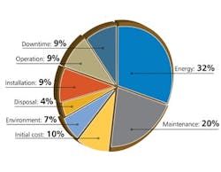
A separate Finnish Research Center study of centrifugal pump performance found that the average pumping efficiency was less than 40% for the 1,690 pumps reviewed in 20 different plants across all market segments. That study also revealed that 10% of the pumps were operating at less than 10% hydraulic efficiency. Considering this sizable efficiency loss, you can expect that from 10% to 20% of the pumps in any continuous process plant are candidates for optimization. More than likely, the real number is much higher.In the largest continuously operating process plants, opportunities for cost reduction—when all aspects of the system are considered —can easily represent millions of dollars and, thus, significantly impact the bottom line.Efforts to improve reliability and achieve optimization of pumping systems invariably involve addressing what is called the “energy and reliability nexus.” In general, mechanical energy in excess of that required for moving process fluid through the pipes is manifested as vibration, heat and noise. This excess energy becomes a destructive force that undermines pump and process reliability.As a result, pump systems routinely have the highest overall maintenance cost compared to other motor systems, including control valves, instrumentation and other types of process control equipment. In addition, pumps and valves are the primary process leak paths for fugitive emissions. LIFECYCLE ANALYSISToday, companies increasingly are relying on lifecycle costing (LCC) for selecting an optimal solution to create economic and environmental value over the life of a system. Using a lifecycle-cost perspective during initial system design will minimize operating costs and maximize reliability. For pump systems, using LCC makes particular sense because the initial purchase price typically represents only about 10% of long-term costs (Figure 2).

TOTAL COST OF PUMP OWNERSHIP

Figure 2. Energy and maintenance costs account for more than half of long-term expenses. Source: Pump costs from a top 10 global chemical manufacturer, FY 2006.

A LCC analysis assesses the cost of purchasing, installing, operating, maintaining and disposing all the system’s components. Determining the LCC of a system involves using a methodology to identify and quantify all the components of the LCC equation. For instance, the equation provided in the Hydraulic Institute’s “Pump Life Cycle Costs: A Guide to LCC Analysis for Pumping Systems” includes terms for initial cost or purchase price (e.g., the pump, pipe, auxiliary equipment); installation and commissioning costs (including training); energy costs (predicted for entire system, including controls); operating costs (labor man-hours for normal system supervision); maintenance costs (e.g., parts, tools, labor man-hours); downtime costs (loss of production); environmental costs (leakage losses and permit violations); and decommissioning costs (disassembly and disposal).Energy consumption is a major element in pump lifecycle costs. Because excess energy consumption leads to higher maintenance costs, these two elements combined typically dominate total lifecycle cost. Thus, it’s important to determine the current cost of energy and the expected annual escalation in energy prices over the system’s projected life, along with labor and material costs for maintenance. Today, pump and automation suppliers, either individually or in partnership, provide customized services to help customers identify, qualify and quantify a pump system’s cost of ownership. Moreover, forward-thinking vendors are viewing their offerings as a holistic package of goods and services, providing the appropriate mix of products, information, training, customer service and personal attention to fully address the customer’s needs. PROPER SIZINGImproper sizing often is the major culprit when it comes to pump inefficiency. Over-sizing of process pumps frequently occurs because parameters aren’t fully defined as the pumps are being specified.Ideally, every pump should operate at its best efficiency point (BEP) at all times but often this isn’t a likely scenario. To maximize the return on an efficiency program, it’s important to know which pumps are most in need of attention and whether they possess far more or less flow capacity than optimum.Consider, for instance, a pump for delivering 5,000 gpm of water at 100 ft. The right-sized pump may offer an efficiency of 70% and require 180 hp (133 kW). If, instead, the pump system is over-sized (excess capacity) and throttled (lower efficiency), efficiency may drop to 40% and brake horsepower may rise to 315 hp (232 kW). That difference of 135 hp or 99 kW (75% excess energy)will contribute to unreliability and poor control performance that continuously degrades over time.Excess energy moving through the system often gives rise to tell-tale symptoms — including a highly throttled control valve in combination with pronounced pipe movement, or even a vibrating catwalk attached to plant infrastructure that’s used to brace the throttled pump. Cavitation inside the pump, control valve or piping itself is a clear indication that hydraulic turbulence or instability exist.
PARALLEL PUMPS

Figure 3. Multiple pumps can cope with fluctuating rates that a single pump can’t handle efficiently.

If the system’s flow is too high coming out of the pump, some users choose simply to throttle the flow using a valve on the discharge side. This is a very inefficient and costly way to configure a system. It increases energy costs for operating the pump, reducing the operating life of the equipment and boosting downtime.Pumps are designed for specific hydraulic flow ranges. When a pump is operating optimally at its BEP, liquid flow is constant and radial forces acting on the impeller are balanced and minimized. As the pump is operated further away from its BEP, the radial and axial loads on the impeller rise. These increased loads can cause shaft deflection, which raises stress on the pump’s bearings and mechanical seal and accelerates the likelihood of pump failures.MONITORING AND MAINTENANCEPump equipment condition is the most important factor for overall system efficiency. Today, various methods exist to monitor temperature, vibration and general health of rotating equipment —and diagnostics are becoming easier.Maintaining reliable pump operations requires deploying a robust program that combines monitoring basic machine-health data in addition to pump operating conditions. The program should address four areas:1. Pump performance monitoring. To better understand how a pump is performing, monitor five parameters — suction pressure, discharge pressure, flow, pump speed and power. Regularly checking suction and discharge pressure is essential for determining the total dynamic head (TDH) and the available net positive suction head (NPSHa), keeping the pump efficient throughout use. Permanent flow meters often are the best option for effective flow monitoring. If you’d like a temporary solution, go with clamp-on flow meters. For power measurements, consider using more than just transducers for monitoring. Assess factors such as input voltage, power factor and motor efficiency to accurately determine the actual shaft horsepower being transmitted to the pump. Pump speed also plays a role —the change in power should be proportional to pump speed.2. Vibration monitoring. The vibration level of a pump directly relates to where it’s operating on its associated performance curve. In essence, high vibration levels indicate poor performance. To avoid future issues, take a vibration reading when a pump is installed. This initial reading provides the baseline for future monitoring. 3. Bearing temperature monitoring. The best way to monitor pump bearing temperature is via a measuring device that contacts the bearing’s outer race. However, there are other, less invasive options, too. One alternative is to use an infrared gun to obtain a temperature reading from the outside of the bearing house. 4. Visual inspections. To detect visual symptoms of pump distress such as cracking, leaking or corrosion, conduct frequent visual inspections; they are an inexpensive way to help save your system from future failures. PROCESS CONTROLAccording to a study of 300 plant energy audits by Emerson Entech, the majority of basic control loops involving pumps (or a set of devices designed to manage the behavior of other devices in a system) actually increase process variability. The primary reason is improper sizing of the pump, control valve and piping — namely, not selecting them in concert to ensure optimum performance — which typically makes tuning the control loop difficult. Automatic control constantly degrades over time as a result of pump and valve mis-sizing issues; as a result, control loops often are switched into manual mode to stabilize the process.Other studies show a high percentage of control loops actually operate in manual mode. A benchmarking report by Honeywell LoopScout of 115 separate facilities across all market segments revealed that, at the worst performers, up to 60% of control loops were “bad actors,” with many of those operating in manual mode.Once you’ve picked a pump to optimize, you can consider a range of mechanical and digital options to help regulate your pumping assets.Mechanical and control modification systems. As Table 1 indicates, using a speed control to help vary speed linearly with an accompanying increase or decrease in horsepower consumption can provide sizable energy savings. Even a small speed reduction could lead to a 30% drop in power consumption. Alternatively, impeller trims (altering the impeller diameter) can change horsepower consumption at a squared rate —offering significant power decreases but not ones as large as from speed changes.
MECHANICAL CONTROL OPTIONS

Source: U.S. Dept. of Energy ITP.

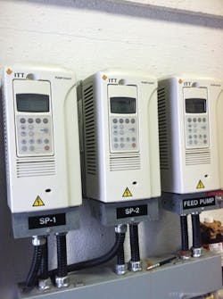
Another mechanical option is installing a parallel system to cope with fluctuation in flow or demand rates (Figure 3). By installing two similar pump systems with parallel piping to handle variable flow rates, plant operators can deal with rates that one pump can’t support alone. Although this may seem like an obvious solution, if the load increases more than the pump was designed to handle, the original pump may be running inefficiently from the beginning.     Electronic control systems. Digital technologies, such as electronic inverters, electronic-only variable frequency drives (VFDs) and variable speed drives (VSDs)that include mechanical devices in addition to electronics, canalter the speed of the pump motor to help improve efficiency. A VFD (Figure 4) is an electrical system that controls motor speed by varying the frequency supplied to the motor. The drive also regulates the output voltage in proportion to the output frequency to provide a relatively constant ratio of voltage to frequency (V/Hz), as required by the characteristics of the AC motor to produce torque. In closed-loop control, a change in power and frequency supplied to the motor alters its speed, thus compensating for a change in process demand. This means greater process control and system efficiency, with even more intelligence integration.Modern VFDs are the most efficient method to change pump speed, with up to 98% electronic efficiency. The simplest of these is the soft starter, a solid-state motor starter that’s used to start or stop a motor by reducing the voltage to each of its phases, gradually increasing the voltage at a fixed frequency until the motor gets up to full voltage/speed. Motors, especially low-voltage ones, have a high initial current (amp draw) when first turned on; this can cause voltage fluctuations and affect the performance of other circuits. Voltage spikes also can damage motor windings. To counteract this issue, you can add components in series to control current in-rush upon startup. In addition, it’s crucial for electronic systems to reside in a climate-controlled environment, which is becoming more common as plants integrate digital systems. More-advanced VFDs or VSDs utilizing frequency inverters can vary the speed of the pump to match the process flow demand. VFDs offer tremendous benefits, including pump size reductions, lower energy costs and improved efficiency. The U.S. Department of Energy estimates that up to 25% of installed motor systems can benefit from retrofitting VSD technology. Despite the known benefits of the technology, initially VFD adoption was relatively slow, primarily due to perceived complexity, reliability and electrical issues. However, today’s more mature VFD technology and cable installation practices largely have mitigated these concerns. As a result, VFD implementation on pump systems is on the rise.
VARIABLE FREQUENCY DRIVES

Figure 4. Units such as these control motor speed by changing the frequency supplied to the motor.

CASE IN POINTWhen evaluating inefficiencies in a pumping system, it’s important to look for tell-tale symptoms of excess energy moving through various subsystems. Often, inefficiency results from a combination of issues that negatively affect equipment integrity and surrounding infrastructure. A vat dilution pump in a chemical process had a 1,180-rpm, 250-hp (187-kW) medium-voltage motor driving a double suction pump. The pump had a 14-in. (35.5-cm) discharge line that branches into three separate lines, each feeding 200°F (93°C) filtrate to separate end-user systems. Each of the 10-in. (25.4-cm) branches had its own 8-in. (20.3-cm) control valves that usually were operating in the range of 20% to 40% open. The gaskets between the pump discharge flange and pipe frequently failed. Looking downstream and up to the top of the chemical towers, the pipes on each branch were rattling, leading to an inordinate number of cracks. Such pipe cracks can cause chemical losses in the sewers, environmental incidents and unplanned downtime. All told, the over-sized pump system averaged one day of downtime per month to repair some component or multiple components. These 12 additional days of unplanned downtime cut into production goals, increased costs and reduced profits. In this case, the financial impact exceeded $1 million annually. Added to that, the company suffered negative publicity both locally and nationally. The primary solution here was implementing VFDs for constant discharge pressure control. The pump system normally consumed around 200hp (149kW), with the end-user valves highly throttled (20%–40% open) and the vibration levels about 0.6 in.(1.5 cm) per second. After VFD implementation, the pump consumes 75 horsepower (56 kW) during normal operation. In effect, the excess 125 horsepower (93 kW), not required to move the fluid, was directly damaging the pump and reducing its reliability. IMPROVE SYSTEM EFFICIENCYUsing LCC to assess pump systems can lead to substantial performance gains. The amount of excess energy, once identified, will serve as the first step in quantifying the value needed for project justification. Then, predict reliability improvements and use past work orders and computerized-maintenance-management-system repair records to estimate annual maintenance costs avoided. Also, evaluate whether better process control can reduce the costs incurred by material variability. Estimate lifecycle savings based on current costs versus optimized ones. The plant of the future will make calculated decisions based on measurable, long-term operating costs and through identifying potential energy drains.

ROBERT LAX is global product manager for PumpSmart Control Solutions at ITT PRO Services, Seneca Falls, N.Y. MIKE PEMBERTON is the energy &reliability program manager for ITT Goulds Pumps/Plant Performance Services, Seneca Falls, N.Y. E-mail them at [email protected] and [email protected].
Sponsored Recommendations

Keys to Improving Safety in Chemical Processes (PDF)

Many facilities handle dangerous processes and products on a daily basis. Keeping everything under control demands well-trained people working with the best equipment.

Get Hands-On Training in Emerson's Interactive Plant Environment

Enhance the training experience and increase retention by training hands-on in Emerson's Interactive Plant Environment. Build skills here so you have them where and when it matters...

Rosemount™ 625IR Fixed Gas Detector (Video)

See how Rosemount™ 625IR Fixed Gas Detector helps keep workers safe with ultra-fast response times to detect hydrocarbon gases before they can create dangerous situations.

Micro Motion 4700 Coriolis Configurable Inputs and Outputs Transmitter

The Micro Motion 4700 Coriolis Transmitter offers a compact C1D1 (Zone 1) housing. Bluetooth and Smart Meter Verification are available.