Remaining competitive today requires achieving higher levels of process performance. At many plants, this demands optimal spray performance over a wide range of operating rates. However, most spray applications receive insufficient attention and design consideration because they are subsystems of unit operations.
Hundreds of applications in the chemical industry rely on sprays — for example, quenching or conditioning gas, injecting catalyst and washing filter cake. The sprays primarily serve to enhance heat and mass transfer or to distribute liquid material over an area or through a volume of gas. Some applications require more than one function to achieve the best process performance. For example, rapid cooling of hot gas not only depends upon a fine average drop size so drops evaporate rapidly but also on drops contacting all the gas. Designs of these systems use multiple nozzles to achieve the contacting and average drops requirements.
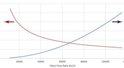
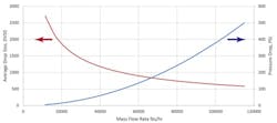
Figure 1. Mass flow rate through a single-fluid spray nozzle significantly affects both pressure drop and average particle size.
Selecting the most-appropriate and cost-effective technology requires thorough process knowledge.
Plants most commonly turn to single-fluid and two-fluid nozzles to achieve a wide range of control. However, spill-return, poppet and pulsing nozzles are gaining wider usage because they offer significant advantages in some applications. So, let’s look at each of these options.
General Considerations
Processes involve a range of operation from startup to full production rate. The maximum design rate is critical but high levels of performance over the entire operating envelope is valuable and, in a growing number of applications, essential. This range of operating conditions requires a range of rates of sprayed material. Most commonly, plants opt for hydraulic or single-fluid spray nozzles because of their low cost, simplicity and good performance at design rate.
Often the performance of a unit operation with a spray is optimized for full rate but the system must operate acceptably over the entire operating range of a facility. In a multi-product plant, the maximum operating rate may vary from one product to another. Consequently, the operating rate of the sprays may change. In addition, the range of actual normal operations may differ from product to product. The result is a process demand for a higher level of spray performance over a wide range of operation.
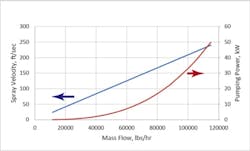
Figure 2. Mass flow rate through a single-fluid nozzle also markedly alters spray velocity and theoretical pumping power.
Many processes require sprays to operate effectively over a 1:10 range of rates. Figures 1 and 2 show the impact of operating rate on spray characteristics of a commercially available single-fluid nozzle. Running a single-fluid nozzle over a 1:10 range results in a nozzle pressure drop that varies by a factor of 100 (Figure 1). The pressure drop can be approximated as a squared function of flow rate. Often, more important to process performance is the average drop size, DV50, which varies from 2,700 microns to 500 microns. The process performance of these sprays differs significantly. The drop evaporation time will be approximately 29 times longer for the larger spray (lower rate operation with 2,700-micron drops). The drop trajectory in a process vessel also changes. The high rate spray has a substantially higher velocity that, when combined with the flow rate, results in a much larger energy input as shown in Figure 2. (In a nozzle, the liquid pressure is converted into the kinetic energy of the spray drops.) The change in the energy input may impact the process dramatically. The high velocity sprays induce bulk gas or vapor motion. The additional gas or vapor motion may cause back-mixing and entrainment of sprays in unintended ways. An approximation of this effect can be calculated from the hydraulic power of the spray.
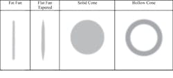
Figure 3. Understanding the pattern required for an application is key step in selecting the most appropriate nozzle.
In contrast, selecting a nozzle with a 40-psi pressure drop for the high flow case would result in only a 0.4-psi pressure drop at the low-flow conditions, causing the spray nozzle to drizzle liquid instead of forming a spray.
For any application, always answer the following questions:
1. What process functions must the spray perform?
2. What spray pattern best matches the application hardware?
3. What spray parameters are critical for this application?
4. What is the required and reasonable range of operation?
The spray pattern is an important consideration in selecting a process spray nozzle. Figure 3 illustrates the common spray patterns. Process applications use solid- and hollow-cone pattern sprays more often than flat fan sprays. The liquid distribution of a solid-cone nozzle is generally better for the circular cross-sections of most process vessels.
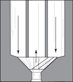
Figure 4. This nozzle gives a hollow-cone spray pattern with a nearly constant average drop size and spray angle over a range of flows.
Choosing the spray pattern is only one part of the process, though. You also must select the number of nozzles to achieve the degree of spray distribution of the liquid. For example, the contacting of a spray quench is an essential part of the design to ensure a uniform outlet temperature. Distribution of spray across a filter cloth for washing or cleaning requires a specific arrangement of nozzles to attain a uniform liquid distribution or spray impact for cleaning.
Selection to produce a wider range of effective spray operation begins with understanding the differing nozzle characteristics. Choosing and designing the method best suited to the process application must integrate the process requirements and constraints. Table 1 provides an overview of five methods, some spray characteristics and the controls required. The range of operation is an approximate guide because each specific unit operation has a different sensitivity to a change in average drop size or drop velocity. The ideal spray nozzle would have the same spray angle, average drop diameter, spray velocity and other characteristics over the operating range — however, no such nozzle exists. Understanding the differences between the options is crucial.
Groups Of Nozzles
One of the most common means to expand the range of single-fluid nozzles and maintain the other parameters is to use multiple nozzles. This approach involves activating another nozzle or a group of nozzles when the process requires additional flow of sprayed material. For example, a system might use ten nozzles, each with one-tenth the total capacity, with the supply pressure controlled at a specific level. This results in the spray average drop size and spray velocity remaining nearly constant. Groups of nozzles require more complex controls to isolate individual nozzles. The issue with this is the effect of the process environment on the nozzle and supply piping not in service and perhaps, more importantly, the process impact on only one nozzle in service. Such a system needs a water flush when the nozzle is removed from service. The distribution of sprayed material in the process changes as more nozzles are put in service.
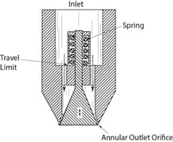
Figure 5. This nozzle uses a spring-loaded element to provide a hollow-cone spray pattern and offers reasonable performance over a high turndown ratio.
Another approach is to have three nozzles designed for low, medium and high capacity service. Only one nozzle operates at a time, starting with the low flow rate nozzle. This robust approach increases the range of the nozzles by opening or closing the valves according to the flow rate required. The control system complexity depends on the process requirements. Because the nozzles have differing capacities, the higher capacity nozzles have a larger average drop size.
The effective operating range depends on operational characteristics, the number of nozzles and each nozzle’s ability to be independently activated.
Spill-Return Nozzle
This is a modified pressure-swirl single-fluid nozzle that recirculates or spills a portion of the nozzle feed, returning it to the suction side of the feed pump (Figure 4). The nozzle produces a hollow-cone spray pattern with a nearly constant average drop size and spray angle over a range of flows. It works in this way because the flow in the swirl chamber is constant. The feed control system is designed to deliver a constant flow to the nozzle and adjust the amount of sprayed material by the back-pressure on the spill connection of the nozzle. The nozzle manufacturer provides a chart or equation describing the operating characteristics, i.e., sprayed flow dependency on nozzle back-pressure, that allows establishing control parameters for a specific nozzle.
This technology currently is gaining wider usage, especially in gas quenching and conditioning applications.
Poppet Nozzle
Such a nozzle uses a spring-loaded element, known as a pintle, to discharge a hollow-cone spray pattern (Figure 5). The pressure of the liquid counteracts the spring to open or close the annular outlet orifice. The nozzle’s key advantage is a reasonable level of performance over a range of operation up to 50:1. The drop size and velocity vary over the operating range. However, the spray angle doesn’t change.
The wide operating range is possible because the spring increases the annular opening around the pintle with increasing flow to the nozzle. When the poppet travel limit is reached, the unit behaves as a fixed-orifice pressure nozzle. However, the poppet nozzle provides a larger drop size at higher flow rates until the travel limit is reached — unlike the fixed-orifice pressure nozzle, which gives a smaller drop size with larger flows.
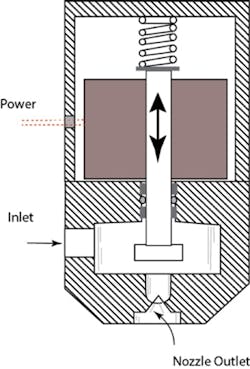
Figure 6. A close-coupled solenoid enables rapid opening and closing of the outlet to control the fraction of time spraying occurs.
Proper sizing of the nozzle to achieve the required performance and flow characteristics includes selecting the spring constant and the travel limit.
Nozzles of this design are used on condensate deaerators that remove dissolved oxygen from water that is fed to a steam boiler.
Pulsed Single-Fluid Nozzle
Pulsing a single-fluid nozzle — that is, rapidly activating and deactivating the nozzle to control the fraction of time it is spraying — enables independent control of flow rate and pressure. A close-coupled solenoid valve acts on the nozzle (Figure 6). When the solenoid retracts the plunger, liquid can spray. The frequency of pulsation varies between the products and manufacturers; it can range from 10 to 200 times per second. The actual flow rate as a percentage of the maximum flow is set via a control unit that supplies the pulsing power to the solenoid valve. The supply pressure must be controlled to set the sprayed flow.
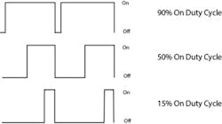
This technology is a relative newcomer to spray options — introduced less than ten years ago. The pulse-width-modulation (PWM) system of spray nozzles (Figure 7) is rapidly gaining traction. It provides a means to maintain the average drop size, spray angle and spray pattern at reduced flows. PWM nozzle systems with controllers provide many advantages for certain applications. For example, adjusting the duty cycle can control the amount of material sprayed onto a conveyor as its speed changes while maintaining the spray parameters.
Figure 7. Even at lower duty cycles a pulse-width-modulation nozzle system maintains the average drop size, spray angle and spray pattern.
PWM nozzles usually are restricted to low-capacity applications, up to 1 kg/min. A second limitation is the design nozzle pressure generally is less than 150 psi; however, some nozzles are available with pressures up to 600 psi and flows up to 25 gpm.
Two Fluid Nozzle
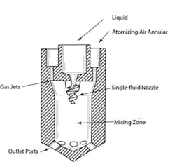
The second most popular option after the single-fluid nozzle, this unit internally mixes the liquid with a gas to intensify atomization (Figure 8). Process applications often rely on nitrogen, steam or other compatible gas instead of air. Adding the atomizing gas can cause process problems because it may need to be removed downstream. The energy cost of the atomizing gas also is a factor to consider.
Air-atomized nozzles can achieve a very wide range of liquid throughputs, 20:1 or higher. However, these nozzles are inherently more complex because of the requirement to control both the liquid feed and the atomizing gas. Directly or indirectly controlling gas-to-liquid ratio (GLR) is essential for tight control of drop size. The spray velocity varies significantly with different nozzle designs and GLR. Back-flow prevention is a critical issue due to the direct connection of the atomizing gas with the process liquid. “Practical Spray Technology: Fundamentals and Practice” describes a number of control practices. (For more details on this book, go to: www.lakeinnovation.com/book_PST.html.)
Figure 8. Air intensifies atomization in this nozzle with multiple outlets but other gases also can be used.
Ensure Effective Performance
We have covered five available methods to expand the operating range of spray nozzles and achieve tight control over a wide range of throughputs. Each method has unique features that must be carefully considered. Table 2 compares the five options.
Selection of the most-appropriate and cost-effective technology requires in-depth process knowledge. Unfortunately, many applications lack adequate monitoring and control instrumentation. Making the economic case for improvements requires understanding both the cost of a nonoptimal operation and the cost of implementing monitoring and control instruments.
Always define turndown of spray nozzles in a specific process context. The generally used values of turndown may be too liberal or too conservative. The number of nozzles needed to achieve the dispersion or the contacting necessary in the process is a crucial aspect of any system.
In addition to the spray nozzle, effective operation requires the integration of spray nozzle control with overall process control.
CHARLES W. LIPP is principal consultant at Lake Innovation LLC, Lake Junaluska, N.C. E-mail him at [email protected].
