An analytical sampling system relies on transport lines to convey fluid from a process stream to an analyzer. The goal is to supply the fluid as efficiently as possible to avoid lengthy time delays between sampling and analysis as well as to minimize sample waste.
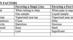
Achieving optimum efficiency is well within your reach. However, success depends on choices you make when designing the sampling system. One of the earliest is about the type of sample transport lines to use to divert flow from the process stream to the analyzer. You can select between two basic types: single-line systems and fast-loop systems. Making an optimal choice requires some knowledge of the design challenges in each case. Table 1 lists some general guidelines for when to choose a single-line system or a fast-loop one. You need not follow all of these recommendations and also may decide to consider other factors. The key is to optimize your selection to fit your real process application.
Source: “Industrial Sampling Systems”
Table 1. Sometimes factors in a specific system will conflict as to the choice but these general guidelines are useful.
Let’s walk through some selection criteria — including sample disposal needs, pressure drop and time delay — that will help you choose the right sample transport line for your application.
Figure 1. This option makes sense for a sample that can be disposed of safely and doesn’t need to be returned to the process. Source: “Industrial Sampling Systems.”
Single-Line Systems
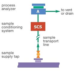
You can use a single-line transport system (Figure 1) only if you don’t intend to return the sample to the process and can dispose of it properly. As shown in Figure 2, the sample is extracted from the process line, transported to a conditioning system if necessary and directed to the analyzer before being disposed of via a vent or drain. As we’ll discuss, multiple variables may force you to use a fast-loop system instead.
Disposal likely won’t pose a problem if the sample is a gas and the full line flow can go to a flare, furnace or stack. For example, you can vent an innocuous sample such as a nontoxic stack gas to the atmosphere. However, many process plants are reducing flaring due to pollution and material waste concerns. These constraints may prevent the flaring of certain gases and, so, may promote returning them to the process via a fast loop.
Figure 2. A single-line system consists of a supply tap from the process stream, any necessary conditioning, an analyzer and a disposal line. Source: “Industrial Sampling Systems.”
Single-line transport is less common for liquid samples, mostly due to disposal problems. You readily can send a low-purity water sample down the drain. However, a less friendly liquid may require an oily sewer, a ground flare, an incinerator or a sample recovery tank. If you can’t find a suitable place to dispose of the sample, you must return the liquid to the process via a fast-loop system.
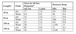
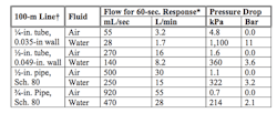
When using a single-line system, you may experience an unacceptable analysis time delay (i.e., one exceeding the 60 seconds or less generally considered satisfactory) that will necessitate moving to a fast-loop system. Tables 2 and 3 offer some typical data for achieving a 60-sec transport time using air or water at varying line lengths and sizes; data for other gases and liquids generally will be similar.
The pressure drop in gas lines usually is negligible, so single lines often work well up to about 100 m. Above this length, the flow rate required to achieve a 60-sec analyzer response may become wasteful because a lot of sample material will be vented. You may have to consider a sample recovery system or a fast loop back to process.
For liquids, pressure drop increases rapidly with line length and can become excessive in single lines longer than about 60 m. If pressure drop appears close to the maximum acceptable, complete a full pressure drop calculation before deciding on a single line. You may need a fast loop instead.
A single line is preferred if your sampling system relies on a vaporizer at the tap. A fast loop generally doesn’t suit such situations.
Figure 3. Such a system can run at a higher flow rate than a single-loop one because most of the flow returns to the process. Source: “Industrial Sampling Systems.”
Single-line systems typically employ 6-mm or ¼-in. outside diameter stainless-steel tubing, although some lines will need larger or smaller tubing. The choice depends on the desired response time and the source pressure available. For example, it’s usually best to use 8-mm or ⅜-in. tubing for stack gas samples.
Avoid using pipe for single-line systems. Its high internal volume causes either slow responses or excessive waste depending on the flow rate used. If pipe is a necessity, as it might be for toxic samples that require the additional protection of a welded pipeline, you probably will need to use a fast-loop system.
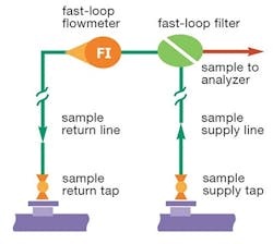
Figure 4. Sample travels at high speed from the sample tap to the analyzer and then returns to the process. Source: “Industrial Sampling Systems.”
Also, remember that the same volumetric flow is required to flush the transport line regardless of sample state. Because liquids are much denser than gases, the mass flow rate of a liquid sample typically is more than 100 times greater than that of a gas sample, depending on the gas pressure. A liquid flowing to waste at 2 L/min adds up to more than 1,000 m3/y of waste. The value of this amount of material and the potential difficulty of its disposal often make a fast loop a better choice for liquid samples.
Fast-Loop Systems
A fast loop (Figure 3) provides rapid responses to process changes by transporting the sample to the analyzer location at high speeds. A fast loop can run at a higher flow rate than a single-line system because most of the flow returns to the process (Figure 4). Fast loops frequently employ tubing or piping with larger bore than single-line systems and often achieve their higher flow rate with less pressure drop. Choose a fast-loop configuration if your process fluid can’t be flared (gas) or drained (liquid) or is too valuable to waste.
A fast loop also makes sense when a single line is too slow or requires more differential pressure (ΔP) than is available at the process, which often is the case for liquid samples when the tap-to-analyzer line distance exceeds 60 m (see Table 2).
Many fast loops use 12-mm or ½-in. outside diameter drawn stainless-steel tubing, although larger or smaller sizes sometimes are necessary. Opt for tubing unless you have a specific reason to install pipe.
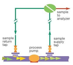
Figure 5. This common fast-loop setup uses a process pump to increase system pressure and speed up sample delivery. Source: “Industrial Sampling Systems.”
In the past, welded pipe was preferred for its additional rigidity and safety. However, it has several disadvantages. At many processing plants, ¾-in. nominal bore is the smallest pipe used; this requires about four times the flow rate of ½-in. tubing. Pipe also has rougher inside walls than tubing, which often increases the pressure drop. In addition, pipe costs more to install and likely will require several elbow bends that further increase the pressure drop in the line. In general, only use pipe if it’s required to meet safety standards.
Most system designers make the fast-loop return line the same size as the supply line. This simplifies construction and also keeps the pressure gradient the same in both lines.
However, if the available ΔP isn’t enough to drive both lines, increase the diameter of the return line. Doing so won’t affect analyzer response time. Process fluid will slow down in the larger bore sample return tap and, therefore, need less driving force. An increase of one tube or pipe size usually suffices to free up most of the available pressure for driving the supply line.
Ideally, the return tap will have a lower pressure than the supply tap. If not, install a check valve somewhere in the return line to prevent backflow. Do your best to avoid using a fast-loop pump because they are expensive and can be unreliable. Choose a return tap location that provides good ΔP; you need enough to drive the desired fast-loop flow.
† Calculated data for ¼-in. outside diameter × 0.035-in. wall tube at ambient temperature
* Atmospheric vent flow for 60-sec response (for gas, line is at 1 barg)
Source: “Industrial Sampling Systems”
Table 2. For single-line systems, pressure drop when handling liquid can become a problem when lines exceed 100 m.
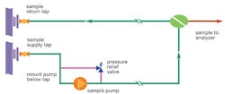
A common arrangement is to take the fast loop from the discharge side of a process pump and return it into the suction side (Figure 5). The higher pressure is particularly good for liquid samples. This approach often works well — even though the returning fluid contaminates the new sample because the old sample mixes with the new fluid as it goes through the pump. However, it slows the response of your sample to a change in stream composition. Ensuring the fast loop doesn’t take more than 5% of the pump discharge flow will prevent a significant delay. This precaution also will guard against overloading the process pump.
If, despite your best efforts, you must use a fast-loop pump, install the return nozzle downstream of the sample take-off point. If the sample is liquid, mount the pump at grade close to the supply nozzle and run tubing one or two sizes larger than the main transport line to the pump suction. The lower fluid velocity will minimize pressure loss on the suction side of the pump and help avoid foaming or cavitation.
† Calculated data for 100-m (328-ft) straight run at 25°C
* Atmospheric vent flow for 60-sec response (for gas, line is at 1 barg)
Source: “Industrial Sampling Systems”
Table 3. As expected, pressure drop decreases as line size increases.
Figure 6 shows a typical installation for a fast-loop pump. For safety purposes, always install a pressure relief valve on the pump discharge, even though it causes dead legs. Keep the dead legs small by using short connections to and from the valve. If the relief valve vents into the pump suction or the return line, set it to open at the desired ΔP, not to the maximum actual discharge pressure of the pump. Don’t allow any flow restriction on either side of the relief valve.
Figure 6. Put the fast-loop pump close to the process tap, mount the return nozzle downstream of the sample take-off point and always install a pressure relief valve on the pump discharge. Source: “Industrial Sampling Systems.”
Making The Right Choice
It’s possible to make informed decisions about whether to use single-line or fast-loop transport lines for your analytical sampling system — but this still involves some trial and error. You may have to guess initially, choosing the design that seems most likely to meet the application requirements. You may base your guess on the considerations outlined in Table 1 as well as on how sample flow rate, time delay, fluid velocity and pressure drop will affect the system. Critical issues that determine your final choice may not become apparent until after the detailed design is underway. Sample system design often goes in circles. It’s all right to change your mind. Just make certain your final design delivers efficient, accurate analyses.
RANDY RIEKEN is market manager for chemical and refining for Swagelok Company, Solon, Ohio. Email him at [email protected].
Managing Sample System Flow
This article is the first in a three-part series on the topic. It was adapted from “Industrial Sampling Systems: Reliable Design and Maintenance for Process Analyzers” (2013), a process sampling textbook authored by Tony Waters and published by Swagelok Company. For more information, visit www.industrial-sampling-systems.com.
