Achieving effective automated control at a plant may well depend upon accurately knowing the level at any given time in a vessel, silo or other container. Unfortunately, with more than 20 technologies for continuous level measurement available, it can be confusing to sort out the most appropriate option for a given application. Variables such as temperature, pressure, vapor density, dielectric properties and many more come into play in making the right selection.
So, in this article, we will look at six technologies — mechanical floats and displacers, differential pressure, capacitance, ultrasonic, radar, and guided wave radar — that are used most often, and provide practical guidance for choosing among them.
The technologies
Let’s start with how the various methods work and their basic advantages and limitations.
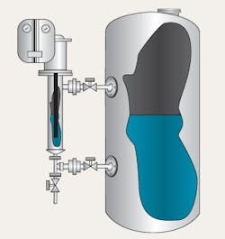
Mechanical floats and displacers. This technology utilizes the Archimedes principle — the buoyant force on an immersed object equals the weight of fluid displaced. When liquid level rises, the weight of the displacer decreases linearly with the level (Figure 1). Outputs can be pneumatic or analog 4-to-20-mA DC.
Figure 1. Such devices are simple and inexpensive but require liquid of constant density.
This type of technology is simple and easy to install, and works well on liquids that are clean. It adapts well to a wide variety of fluid densities.
However, the fluid density must not vary, because the float or displacer is sized to the density of the liquid. If the density changes, then the weight of the displaced material changes, necessitating re-calibration. Another limiting factor for mechanical technology is build-up of material on the displacer or floats. This build-up also will cause a change in weight displacement and require re-calibration or cleaning of the displacer.
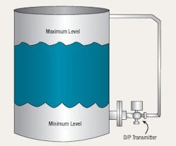
Differential pressure. The high pressure side of a differential pressure instrument is connected to the bottom of a tank and the low pressure side to the vapor space at the top of the vessel (Figure 2). The measured differential is the pressure head of the liquid in the tank. This is a true liquid level indication, if density doesn’t change.
Figure 2. The pressure difference between taps indicates the liquid head in the vessel.
A differential pressure transmitter suits liquids that are relatively clean and free of suspended solids. It is readily installed on a vessel and can be removed with the use of block valves.
However, it is of vital importance that liquid contents maintain a constant density. Density changes, such as those caused by variations in temperature or chemical make-up of the liquid, induce errors and mandate re-calibration.
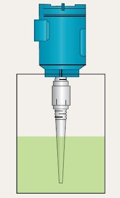
Capacitance. Here, a contacting metal probe, usually lined with a sleeve of inert chemical-resistant material like PTFE, is attached to electronics with either a fixed or a variable frequency oscillator circuit. Application of a constant voltage to the rod or sometimes a flexible cable results in a frequency that infers level (Figure 3).
Figure 3. This technology can handle a wide range of applications but is intrusive.
This technology can handle a broad range of applications from cryogenics to extremely high temperatures and pressures, requires only one opening, usually at the top of the container, and has no moving parts to plug or wear out over time. For a conductive or water-based fluid, the application is relatively easy, with only an initial calibration needed unless a conductive coating clings to the probe.
The geometry of the container and other factors can complicate getting proper results. Moreover, capacitance is an intrusive measurement; so chemical compatibility with the vessel contents must be taken into account, as well as the potential for build-up problems. Additionally, for non-conductive or insulating fluids like hydrocarbons, the liquid chemistry must remain constant or homogeneous. Changes in material properties due to temperature or chemical make-up cause the dielectric property of the material to change, incurring errors and necessitating re-calibration.
Ultrasonic. This technology works by providing voltage to a piezoelectric crystal that sends sound waves through the air to the liquid or solid surface where reflection back to the transducer takes place (Figure 4). The distance, which is proportional to the travel time, relates to level. Ultrasonic technology, because of advancements in electronics and echo-processing software, has become one of the best options for continuous level measurements.
Figure 4. Chosen for environments containing heavy dust or high humidity.
The technology measures from the top down; so there is virtually no contact with the contents of the container. Non-contacting technologies incur fewer problems with build-up, direct chemical attack and thus corrosion, and give a more consistent measurement. Ideally liquid should be homogeneous, with the temperature throughout the container fairly constant. In many cases, ultrasonic can measure solids, thanks to the ability of good signal-processing software and the use of flexible aimers for materials producing angles. Configuration, which was an issue years ago, now has become simple.
However, changes in vapor density, high dust content, foam, electrical and ambient noise, and surface turbulence can affect the speed of the transmission pulse. For instance, a heavy vapor cloud emitted above the liquid surface and creation of stratification layers will cause errors in the reading or produce a loss of signal transmission back to the transducer face. Ultrasonic cannot be used at temperatures exceeding 300°F.
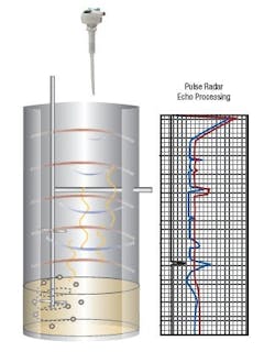
Radar. There are different techniques of propagating radar, such as pulsed and Frequency Modulated Continuous Wave (FMCW). Pulsed wave radar is similar to ultrasonic non-contact technology, but with the signal traveling at the speed of light instead of sound. In pulse radar, microwave signals are evaluated by a method of sequential sampling of discrete echoes over time (Figure 4).
The FMCW technique sends hundreds of thousands signals at different frequencies in a short time and compares those frequencies from transmit to reception, using Fast Fourier mathematics to determine level.
Measuring solids generally is the most difficult application for level; radar technology is becoming the norm for reliable measurement and dealing with the angles of repose of the material, dust in the airspace, and long-range readings.
The technology is non-contacting. Moreover, radar is unaffected by airspace conditions like humidity, heavy vapors, and vapor-layer stratification due to temperature fluctuations. It can perform measurements out to 230 ft. in conditions of heavy dust, which other technologies find very difficult. There are now two-wire, loop powered designs that offer low cost of wiring and ownership. Plus, prices have considerably lowered. For solids’ measurement, most radar transmitters will offer different antenna options. The horn (4 inches in diameter) is most widely used, but parabolic or dish type antennas also are available.
The accuracy of radar technology depends upon the dielectric constant of the material, which affects the reflectivity of the radar wave. A lower dielectric value (such as 1.5 compared to air’s 1.0) will lessen the amplitude or strength of the microwave signal reflecting back to the antenna mounted at the top of the vessel, making the measurement difficult. Radar cannot measure the interface of two immiscible liquids like oil and water. There also are pressure limitations for the antenna seal as well as temperature limitations at the flange area based on the material of the emitter, propagation tip or rod-style antenna.
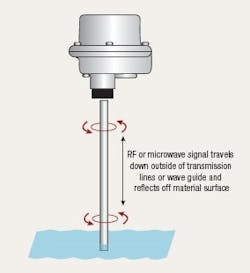
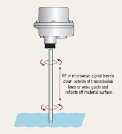
Guided wave radar. Sometimes referred to as Time Domain Reflectometry (TDR), this technology is similar to non-contact radar, except that it is invasive. Guided wave radar utilizes a flexible cable or various types of rigid probes and generates microwave pulses down the probe or guide (Figure 5).
Figure 5. This technology offers a measurement span that almost equals the vessel height.
When the signal meets the liquid or solid, it is reflected back, with the time from launch to reception a measure of the distance. Like non-contact radar, the amplitude of the signal depends upon the conductivity and dielectric value of the material. This technology has become very successful for measuring solids such as powders in hoppers and bins where the measurement range is 30 ft. or less.
Guided wave radar is unaffected by temperature, pressure or vacuum, and changes in the airspace with vapor. Additionally, the accuracy is independent of the material’s dielectric value, conductivity, density, and moisture content. Another distinct advantage is that calibration can be done without material being present. The technology tends to work well for short-range measurements. Because it has little top-end and bottom-end blanking, this technology can measure from near the top to almost the bottom of the container.
As a contact technology, it poses concerns about material compatibility, which sometimes necessitates expensive, exotic metals. Installation can be quite cumbersome with the rigid probe styles for liquid applications if head space above the vessel is limited. Additionally, the technology can be difficult, if not impossible, to apply to agitated vessels. In solids’ applications, there is a risk of the flexible cable being broken from too much loading of material weight. The loss of a guided wave radar cable into a powder-like material can cause heavy damage to a screw conveyor at the bottom of a silo. Also, abrasiveness of the material as well as excessive coating can cause damage and wear or false readings.
Selection criteria
Now that we’ve examined how these various technologies work and their basic advantages and disadvantages, we are ready to see how they compare for a given application. To do this properly, the application must be understood in full. Then, use the following criteria to use to target the most appropriate choices:
- range or height of measurement;
- accuracy and repeatability;
- material to be measured;
- type of measurement (continuous level, interface or point level);
- physical or chemical changes to material in container;
- vapors in the airspace with temperature changes or heavy dust;
- material of container;
- pressure and temperature (minimum and maximum);
- dielectric constant;
- mounting constraints or available container openings (size, type and rating);
- desired output or information from field device (control or simple readout);
- solids or liquids to be measured; and
- potential material build-up.
After reviewing these criteria, you should have narrowed the list of potential technologies. Then you may want to delve into some other factors, such as cost of ownership and direct costs. Typically, a number of technologies can be successfully applied to an application. The important thing to remember is that all technologies work when properly applied. Don’t force fit a technology into an application or you’ll be setting yourself up for problems. Always give special consideration to the principle of operation and where the limitations of each technology lie.
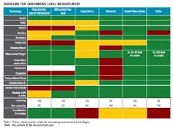
The Table relates key criteria for a continuous level measurement to the various technologies and so will help you select the appropriate options. The color coding within the cells gives an indication of how well the technology fits the criterion, with green meaning okay; yellow, caution (also look at an another technology); and red, no good (use an alternative technology).
Table 1. These criteria provide a basis for winnowing measurement technologies. (Click to enlarge.)
*Note: This pertains to the measurement span.
Once you’ve narrowed the choices using the general criteria in the chart, consider your particular needs. Here, application data sheets offered by companies that provide a variety of level technologies can serve as a useful tool. They raise questions that can lead you to the proper technology for the measurement at hand
Do your level best
Choosing the right technology for continuous level measurement requires an appreciation of the applicability and pros and cons of the various options. It also demands an understanding of the attributes of the material to the monitored and the environment in which measurements will take place. Armed with this information, it becomes easy to determine the appropriate measurement technique for the application.
Jerry Boisvert is a product marketing manager for Siemens Energy & Automation, Grand Prairie, Texas. E-mail him at [email protected].