Heat integration steps can present control problems
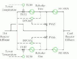
There, effluent from a hydrotreater reactor reboils two downstream towers. Flow bypass around the reboilers controls the reboiler duty. Figure 1 shows the planned control scheme. The temperature of a tray up the tower is used to manipulate a temperature control valve (TV) upstream of each reboiler. This varies the reactor effluent flow to each exchanger. A differential pressure controller (DPC) adjusts the reactor effluent flow through each leg of the bypass line to downstream of the corresponding reboiler.
Figure 1. This is the way the differential pressure controllers and valves were meant to be linked.
Using temperature control would have been difficult. Phase change is occurring throughout the heat integration circuit on both the reactor feed and reactor effluent side. Small measured temperature differences would represent large shifts in duty.
The control objective was to have equal duties in each leg of the heat integration system. Process needs made the duty of Reboiler One approximately 1.5 times that of Reboiler Two. Optimal operation required balancing the heat loads to get equal inlet temperatures upstream. The ability to set different values for the two DPC loops was supposed to allow for bias control on the entire system.
Charitably, this would be described as a difficult system to control. Each combined temperature-control-valve/reboiler system is being treated as a head flow meter element to adjust a second control valve. The bias between the differential pressure readings on both flow loops would require constant re-setting for accurate control. Due to the pressure balance, small changes in valves TV47 and TV53 have a large impact on the flow split. For example, a change of 3.6% of system pressure drop (or 2 psi) across TV47 would change the amount of flow through that loop by almost 21%. To add an extra level of complexity, the larger temperature control valve had been installed on the loop for the smaller duty.
Difficult to control as it was, this arrangement might have sufficed. In practice, though, the control system continuously hunted. Operators were constantly intervening to reset valve position and flow rates. The system performed much worse than anticipated.
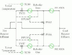
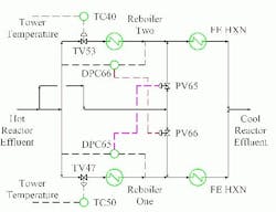
A careful check of the documentation was illuminating. The process flow diagrams, piping and instrumentation diagrams, isometric drawings, and control computer documentation didn’t agree with each other. They contained different configurations of the control links between the flow loops for DPC65/66 and PV65/66. Field verification revealed that the unit was actually configured as shown in Figure 2.
Figure 2. Linking controllers and valves with same numbers was logical — but wrong here.
DPC66 controlled valve PV66 and DPC65 controlled valve PV65. It’s logical to link the control signal to the valve with the same number. Most plants use this protocol for instrument loop numbering. This plant didn’t, however. Numbers for control signals routinely differed from those for control valves. The correct control linkages should have been DPC66 to PV65 and DPC65 to PV66. The root cause of the error appeared to be mistakes in valve numbering on the piping and instrumentation diagrams and isometric pipe drawings. Undoing the cross-connect and putting the system back to the designed configuration (Figure 1) significantly improved unit control.
By Andrew Sloley, contributing editor, [email protected], and
Carolyn K. Hawley, VECO USA, [email protected].


