Is your chemical process "covered" by 29 Code of Federal Regulations (CFR) 1910.119, which covers the process safety management of highly hazardous chemicals? If so, you might be aware that instrumentation and controls can be several of the many independent layers used to maintain process safety.
A number of new domestic and international standards and guidelines are available in this area.1-3 The Occupational Safety and Health Administration (OSHA) has publicly recognized American National Standard Institute/Instrumentation, Systems, and Automation Society (ANSI/ISA) 84 as a "good engineering practice" and acceptable when following the 1910.119 regulation. Unfortunately, many engineers are either unaware of or reluctant to follow these documents. Ignorance is not bliss, or an adequate defense in court should something go wrong.
These standards and guidelines either frown on or actually forbid performing control and safety in one "box" ," e.g., a distributed control system (DCS). However, many plant engineers combine control and safety for purely economic reasons ," fewer systems, single source of supply, etc. ," without realizing the negative impact on safety.
Safety cannot be shortchanged ," no easy solutions exist. Current standards address this with a design life-cycle approach that consists of a set of procedures starting with the process conceptual design and ending with decommissioning.
The design of instrumentation and control systems for safety has been a source of controversy for the past 15 years. What technology is most appropriate (e.g., relay, solid state, software)? What level of redundancy is most appropriate (e.g., single, dual, triple)? What manual test interval is most appropriate (e.g., monthly, quarterly, yearly)? Should safety control be performed in the main control system?
These questions cannot be answered subjectively because everyone has a different opinion and personal background. Developers of industry guidelines, standards and recommended practices realize this problem and have created performance-based documents. In other words, the standards do not mandate the technology, level of redundancy or test intervals. The common theme in all the documents is: The greater the level of process risk, the better the systems needed to control it.
Multiple safety layers
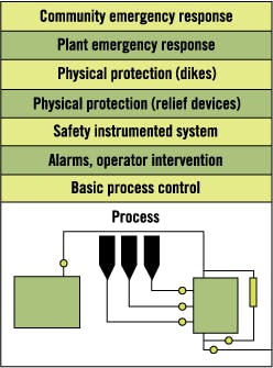
One common theme in all of the industry's process safety documents is multiple independent protection layers. Instrumentation and controls form many of these layers. See Fig. 1.
Figure 1. Independent Protection Layers
Historically, all of the layers were independent, typically using diverse technologies from diverse vendors. However, with the acceptance of software programmable systems, many plant engineers have considered combining multiple functions into one system. For example, it is possible to combine control, alarms, shutdown and fire and gas systems in a modern DCS.
The benefits seem obvious ," single source of supply, simplified training and spare parts, lower installed costs, etc. ," yet all industry standards either outright forbid or strongly frown on such practices. The reasons are simple. How do you allow access to some functions, but deny access to others? How do you enforce management-of-change policies when operators are constantly making changes to the control system? How can you be certain changes made in one program area will not impact the functionality somewhere else?
What might go wrong?
One end-user reported a case in which all the safety functions in one facility were performed in the DCS. Plant personnel were not aware of the recent industry standards. The corporate specialist mandated that all safety loops be verified. After checking, plant personnel found one-third of the loops had been deleted, one-third were bypassed, and the remaining one-third did not function when tested.
The benefits of multiple independent layers also can be shown graphically. Consider an example of a process with an inherent level of risk ," in this case, the probability of an explosion ," of once per year, (as was common in the manufacture of gun powder more than a century ago). Such a level of risk would not be tolerated today.
Suppose the current goal was a 1/100,000 chance of explosion. Assume the basic process cannot be changed. The only alternative would be to add multiple independent protection layers. See Fig. 2.
Figure 2. Risk Reduction
The "mechanical" layer might represent pressure-relief valves, and the "other" layer might represent a fire and gas system. Some layers are "prevention layers," installed to prevent a particular hazard, while others are mitigation layers, installed to lessen the consequences of a particular incident. Assume each layer reduces the risk by a factor of 10. The original accident probability of once per year now can be reduced to 1/100,000 per year (10 x 10 x 10 x 10 x 10 = 100,000).
But what if most of the layers were performed in a single box such as a basic process control system (BPCS). In this case, the overall risk would be reduced only by a factor of 100 (the control system and the mechanical protection [10 x 10 = 100]). The overall level of safety protection in this scenario is less by a factor of 1,000, even though a modern control system was used. Industry standards actually limit the performance operators can claim from a control system to no more than a factor of 10.
Design life cycle
A detailed, systematic, methodical, well-documented design process is necessary for the design of safety instrumented systems. This starts with a safety review of the process, implementation of other safety layers and a systematic analysis, as well as detailed documentation and procedures. The steps are described in the standards and referred to as a safety design life cycle. The intent is to leave a documented, auditable trail, and to make sure nothing falls between the inevitable cracks within every organization.
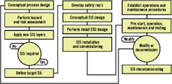
Fig. 3 shows the life-cycle steps described in the ANSI/ISA 84 standard. This should be considered one example only, because variations of the life cycle are presented in other industry documents. A company can choose to develop its own variation of the life cycle, based on its unique requirements.
Figure 3. Safety Life Cycle
Some will complain that performing all the life-cycle steps, like all other tasks designed to lower risk, will increase overall costs and result in lower profitability and decreased productivity. One in-depth study, conducted by a group that included major engineering societies, 20 industries and 60 product groups, concluded that production increased as safety increased.4 OSHA has reported similar findings.
Conceptual process design. The first step in the life cycle is to develop an understanding of the process, the equipment under control and the environment in sufficient depth to enable the other life-cycle activities to be performed. The goal is to design an inherently safe plant. The activities in this step are generally considered a job for a process engineer.
Hazard analysis & risk assessment. The next step is to develop an understanding of the risks associated with the process. These can impact personnel, production, capital equipment, the environment, company image and more.
A hazard analysis consists of identifying the hazards. Numerous techniques can be used (HAZard and OPerability study [HAZOP], what if, fault tree, checklist, etc.) and numerous texts describe each method.5-7
A risk assessment classifies the risk of the hazards identified in the hazard analysis. Risk is a function of the frequency or probability of an event, as well as the severity or consequences of the event.
A risk assessment can be either qualitative or quantitative. Qualitative assessments subjectively rank the risks from low to high, while quantitative assessments attempt to assign numerical factors such as death or accident rates to the risk. This is not intended to be the sole responsibility of the control system engineer. A number of other specialists are required to perform these assessments, including risk analysts, process designers, process engineers and possibly control engineers.
The goal of process plant design is to have a plant that is inherently safe, or one in which residual risks can be controlled by the application of noninstrumented safety layers.
If the risks can be controlled to an acceptable level without the application of an instrumented system, then the design process stops, as far as a safety instrumented system is concerned. If the risks cannot be controlled to an acceptable level by the application of noninstrumented layers, then an instrumented system will be required.
The most difficult step in the overall process for most organizations seems to be determining the required safety integrity level (SIL). This is not a direct measure of process risk, but instead a measure of the safety system performance required to control the risks identified earlier to an acceptable level. The standards outline a variety of methods that describe how this can be accomplished.
Safety requirement specification development. The next step consists of developing the safety requirements specification, essentially the functional logic of the system. Naturally, this will vary for each system. No general across-the-board recommendation can be made.
Each safety function should have an associated SIL requirement, as well as reliability requirements if unplanned shutdowns are a concern. The engineer should include all operating conditions, from startup through shutdown, as well as maintenance.
The system will be programmed and tested according to the logic determined during this step. If an error is made here, it will carry through for the rest of the design. It will not matter how redundant the system is or how often the system is manually tested; it will not work properly when required. These are referred to as systematic or functional failures.
Conceptual SIS design. The purpose of this step is to develop an initial design to determine if it meets the safety requirements and SIL performance requirements. The engineer needs initially to select a technology, configuration (architecture), test interval, software design, power source and user interfaces, among others, pertaining to the field devices and the logic box.
Factors to consider are overall size, budget, complexity, speed of response, communication requirements, interface requirements, methods of implementing bypasses and testing. Plant personnel then can perform a relatively simple quantitative analysis to see if the proposed system meets the performance requirements.8-11 The intent is to evaluate the system before specifying the solution. Just as it is better to perform a HAZOP before building the plant, it is better to analyze the proposed safety system before specifying it ," how else will you know if it meets the performance goal?
Detailed SIS design. Once a design has been chosen, the system must be engineered and built following strict and conservative procedures. The process requires thorough documentation ," an auditable trail someone else can follow for verification purposes.
Installation and commissioning. This step ensures the system is installed per the design and performs per the safety requirements specification. Before a system is shipped from the factory, it must be thoroughly tested for proper operation. If any changes are required, they should be made at the factory, not at the installation site.
At installation, the entire system ," including field devices ," must be checked as well. A detailed installation document should outline each procedure to be carried out. Finished operations should be signed off in writing to verify each function and operational step has been checked.
Operations and maintenance. Every system requires periodic maintenance to function properly. Not all faults are self-revealing, so every safety system must be periodically tested to make sure it will respond properly to an actual demand. The frequency of inspection and testing should have been determined earlier in the life cycle. All testing must be documented.
Modifications. As process conditions change, it will be necessary to make changes to the safety system. All proposed changes require returning to the appropriate phase of the life cycle. A change considered minor by one individual could have a major impact on the overall process. The change must be thoroughly reviewed by a qualified team. Many accidents have been caused by a lack of review.12
Decommissioning. System decommissioning should entail a review to make sure system removal will not impact the process or surrounding units, and that means are available during the decommissioning process to protect the personnel, equipment and environment.
Conclusion
When it comes to the design and evaluation of instrumentation and control systems installed for safety purposes, no easy answers exist. Triplicated logic boxes do not magically solve all problems. A methodical, team-oriented life-cycle approach is required.
Gruhn is owner of L&M Engineering, Houston. He can be reached at paul.gruhn @ix.netcom.com.
References
1. International Society for Measurement and Control. Application of Safety Instrumented Systems for the Process Industries, ANSI/ISA 84.
2. International Electrotechnical Commission (IEC). 61508 and draft 61511 standards.
3. American Institute of Chemical Engineers, Center for Chemical Process Safety (AIChE CCPS). Guidelines for Safe Automation of Chemical Processes, 1993.
4. Leveson, Nancy G. Safeware ," System Safety and Computers, Addison-Wesley, 1995.
5. AIChE CCPS. Guidelines for Hazard Evaluation Procedures, 1992.
6. AIChE CCPS. Guidelines for Chemical Process Quantitative Risk Analysis, 1989.
7. Taylor, J.R. Risk Analysis for Process Plants, Pipelines and Transport, E&FN Spon, 1994.
8. Safety Instrumented System (SIS) ," Safety Integrity Level (SIL) Evaluation Techniques, ISA Draft Technical Report dTR84.02, 1997.
9. Gruhn, P. "The Evaluation of Safety Instrumented Systems ," Tools to Peer Past the Hype," ISA transactions 35 (1996) 25,"32.
10. Gruhn, P. "Safety Systems: Where is Your Weak Link?" InTech, December 1993.
11. Smith, D. J. Reliability, Maintainability and Risk, Butterworth Heinemann, 1993.
12. "Out of Control ," Why Control Systems Go Wrong and How to Prevent Failure." Health & Safety Executive (U.K.), 1995.


