Piping systems — pipes, fittings, valves and other items — not only must convey fluids (liquids and gases) from one location to another but also must cope with mechanical stresses. So, it is essential to check a system’s mechanical behavior under regular loads (internal pressure, thermal stresses, dynamic forces, etc.) as well as under occasional and intermittent loading cases such as special vibration or pulsation. This evaluation usually relies upon commonly used rules and guidelines or involves review by an expert; sometimes specialized software performs the piping stress analysis. Typically, pipe stress engineers verify that the routing, nozzle loads, hangers and supports are appropriate and adequate to ensure allowable pipe stress isn’t exceeded during situations such as sustained operations, pressure testing, etc.
Localized stresses in piping systems and their supports demand attention because they can lead to different types of failures. Such high stresses in steel structures and piping components can arise, for example, from sharp corners in the design or inclusions in a material.
Another area of concern is operating temperature range; piping and its supports for high or very low operating temperatures require special designs. High temperature poses issues of strength of materials, thermal expansion and thermal stress. Low temperature brings its own set of rules and guides; for instance, most ordinary steels become more brittle as the temperature decreases from normal operating conditions. So, it’s necessary to know the temperature distribution for these applications and select materials accordingly.
Piping Design And Layout
An elbow provides a change in direction in a piping system. This adds pressure losses to the system due to impact, friction and re-acceleration. As fluid enters the inlet of an elbow, it typically continues moving straight ahead to the first (or primary) impact zone; the fluid then is deflected at an angle toward the outlet of the elbow. Many different factors, such as the elbow design and the fluid’s characteristics and velocity, determine the deflection angle. In many designs, the fluid will hit one or more secondary impact zones before exiting the elbow.
Elbows and bends are available in a variety of angles and types. For instance, 90° elbows come in short and long radius versions. Short radius elbows have a center-to-face dimension of 1 × diameter and typically are used in tight areas where clearance or space is an issue. Long radius elbows have a center-to-face dimension of 1.5 × diameter; they are the more common type and are used when space is available and flow is more critical.
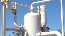
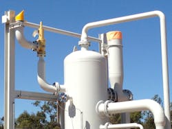
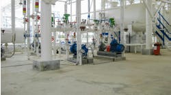
Reducers provide a change in pipe diameter. They are either concentric (Figure 1) or eccentric. Concentric reducers retain the existing pipe centerline, while eccentric ones shift the centerline. Eccentric reducers are useful, for example, to maintain elevation bottom-of-piping (BOP) in a piping system or with flat-side-up (FSU) in a pump suction to avoid problems such as gas pockets.
Figure 1. This piping system uses a number of concentric reducers.
The design of piping branch connections is a critical task; poor arrangements have caused numerous failures. Coming up with a proper design requires a great deal of effort; many issues, such as fluid dynamics, mechanical robustness and localized stresses, come into play. The general rule (with some exceptions) is to use a top-side branch connection when the fluid is a gas, and a usually a bottom-side branch connection when it is a liquid. However, many factors, including application and fluid details, influence the selection. For example, a low temperature service (whether liquid or gas) typically should have a top-side branch connection to cope with the possibility of ice formation within the pipe during normal operation; the ice, which would flow at the bottom of the pipe, could block a bottom-side connection.
Fluid hammer is an important consideration for many piping system designs. When the flow through a system is suddenly halted at one point, because of a valve closure, machinery trip (such as a pump trip) or another reason, the fluid in the remainder of the system doesn’t stop instantaneously. As fluid continues to flow into the area of stoppage (upstream of the valve or machinery), it compresses, causing a high pressure situation at that point. Likewise, on the other side of the restriction, the fluid moves away from the stoppage point, creating a low pressure (vacuum) situation at that location. The fluid at the next elbow or closure along the piping system is still at the original operating pressure, resulting in an unbalanced pressure force acting on the valve seat, the elbow or the stoppage location. The fluid continues to flow, compressing (or decompressing) fluid further away from the point of flow stoppage, thus causing the leading edge of the pressure pulse to move through the piping. As the pulse passes the first elbow, the pressure now is equalized at each end of the pipe run, leading to a more-or-less balanced pressure load on the first piping leg. However, the unbalanced pressure now has shifted to the second leg. The unbalanced pressure load will continue to rise and fall in sequential legs as the pressure pulse travels back to the source (or forward to the sink). The ramp-up time of the profile roughly coincides with the elapsed time from full flow to low flow, such as the closing time of the valve or trip time of the machinery. Because the leading edge of the pressure pulse shouldn’t change as the pulse travels through the system, the ramp-down time is more or less the same; the duration of the load from initiation through the beginning of the ramp-down approximately equals the time required for the pressure pulse to travel the length of the piping leg. Piping design must consider these issues as well as other operating parameters such as how fast a change (such as closing of a valve) could be.
Once the piping layout is complete, attention should turn to piping support design and stress analysis.
Piping Support Design
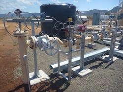
Sustained loads on supports mainly consist of internal pressure and deadweight — i.e., the weight of pipes, fittings, components such as valves, operating or test fluid, insulation, cladding, lining, etc. The first step in piping support design is to determine the allowable span between supports; this span depends on many details, such as piping material and wall thickness (pipe schedule), and generally includes a conservative safety factor. As a very rough indication, allowable spans between supports for 2-in., 6-in., 10-in. and 20-in. piping could be 3 m, 5 m, 7 m and 9 m, respectively. As another rough indication, you can conservatively estimate the allowable span as 2×D0.5 where D is the pipe diameter in inches and the resulting allowable span is in meters. Some tables and charts give spans between supports 20–30% greater than these values but I encourage more conservative numbers. Wherever a valve, fitting, strainer, flange connection, instrument or other heavy object is in the piping system, reduce the allowable span accordingly. Adding extra piping supports near valves and flange connections always is a good idea (Figure 2).
Figure 2. It’s good practice to have supports near valves and other heavy items attached to piping.
Movement of the piping must be controlled. A fixed-point anchor restricts all axial and rotational movements whereas a cross guide constrains displacements of piping along the axis perpendicular to its centerline. Support design should consider many details, such as the type of machinery connected to the piping, details of the machinery package, nearby equipment and other items attached to the piping. For example, machinery packages that include shell-and-tube heat exchangers (e.g., oil and water coolers, inter/after coolers, etc.) should have an anchor support on the side from which the tube bundle will be pulled out for maintenance work and also should consider the thermal expansion of piping connected to the exchanger(s).
Typical vertical supports to carry deadweight are:
• support hangers;
• rod hangers;
• resting steel supports; and
• variable and constant spring hangers (which should be used where other options aren’t effective).
Rod hangers and resting steel supports fully restrain downward pipe movement but permit pipe to lift up. Variable spring hangers usually use coiled springs to support a load and allow piping movement; the resistance of the coiled springs to a load changes during compression. In contrast, a constant spring hanger provides consistent support force by having two moment arms pivoted about a common point. The load is suspended from one of these arms and a spring is attached to the other. An appropriate choice of moment arms and spring properties can provide a resisting force nearly independent of position. Constant support hangers principally are used to support pipes and equipment subject to vertical movement due to thermal expansion (or contraction) at locations where transfer of load/stress to other supports or equipment can be critical. As an indication, the maximum recommended variation from the operating load is around 25–30% for variable spring hangers. If the variation exceeds 30%, a constant support hanger might be used.
Undesirable movements can occur due to many phenomena, such as sympathetic vibration, rapid valve closure, relief valve opening and two-phase flow. It may be necessary to limit this type of deflection to prevent generation of unacceptable stresses and high loads on equipment nozzles. A sway brace, which essentially is a double-acting spring housed in a canister, is a cost-effective means of restricting pipework deflection. It isn’t intended to carry the weight of piping systems but only to limit undesirable movements. It acts like a rigid strut until a small preload is reached, then the restraining force increases in proportion to the applied deflection. A sway brace does provide some resistance to the thermal movement of a piping system; so specifying it requires care. Installation of a sway brace raises the fundamental frequency of vibration of a pipework system, which likely will reduce undesirable deflections. The devices often are used to solve unforeseen problems of resonant vibration.
Piping systems also may face loads imposed by occasional events such as severe wind, earthquake or a fluid hammer. To protect piping from wind or earthquake (which usually occur in a horizontal plane), normal practice is to attach lateral supports (instead of axial restraints) to piping systems. Protecting piping from fluid hammer loads may call for both lateral supports and axial restraints.
To carry sustained loads, vertical supports normally are required. For thermal loads, having no supports gives zero stresses — so, the fewer the number of supports, the lower the thermal stresses. Only use axial restraints and intermediate anchors to direct thermal growth away from equipment nozzles.
Pipe Stress Analysis
Such an evaluation is an important step for machinery piping designs as well as many piping systems. In simple terms, it is used to:
• Ensure the stresses in all piping components (including piping supports) in machinery package(s) and connected systems are within allowable limits;
• Solve dynamic problems developed due to mechanical vibration, pulsation, etc.; and
• Address issues, such as displacement stress range, nozzle loading, etc., due to higher or lower operating temperatures.
Internal pressure, whether design or operating, usually causes uniform circumferential stresses in the pipe wall; pressure/temperature ratings enable determining the appropriate pipe wall thickness. Internal pressure also gives rise to axial stresses in the pipe wall. These axial pressure stresses depend upon pressure, pipe diameter and wall thickness. Because all three are set at initial stages of design, the axial stresses can be determined at that point; changing the piping layout or the support scheme usually can’t alter these stresses. A pipe’s deadweight causes it to bend (generally downward) between supports and nozzles. This produces in the pipe wall so-called bending stresses, which vary more-or-less linearly across the pipe cross-section — being tensile at either the top or bottom surface and compressive at the other surface. If the piping system isn’t supported in the vertical direction (i.e., in the direction of gravity) except for equipment nozzles, pipe bending due to deadweight may create excessive stresses in the pipe and impose large loads on equipment nozzles, thereby increasing susceptibility to “failure by collapse.” Various international piping standards and codes impose stress limits on these axial stresses generated by deadweight and pressure to avoid problems; to keep calculated actual stresses below such allowable stresses for sustained loads may require provision of more supports for the piping system.
Thermal loads (expansion and contraction loads) are important forces in piping design; Piping will expand or contract as it goes from one thermal state to another, e.g., from ambient conditions (while idle) to normal operating temperature and then back to ambient. If the piping system isn’t restrained in the thermal growth (or contraction) directions — for example, in the axial direction of pipe — then, for such cyclic thermal loads, the piping system expands or contracts freely. In this case, no significant internal forces, moments and resulting stresses and strains result. If, on the other hand, the piping system is restrained in the directions it wants to thermally deform, such as at equipment nozzles and pipe supports, cyclic thermal stresses and strains develop throughout the system as it goes from one thermal state to another. When such calculated thermal stress ranges exceed the allowable thermal stress range specified by various international piping standards or codes, then the system is susceptible to “failure by fatigue” or other modes of failure.
To avoid such failures due to cyclic thermal loads, the piping system should be made flexible. This often involves introducing bends or elbows into the layout to add flexibility. Having connected equipment nozzles offset from each other provides one avenue for this. If the two nozzles are in line, then the straight pipe connecting these nozzles will be very stiff. In contrast, offset nozzles will require piping with a bend or elbow; such an “L-shaped” piping layout is much more flexible. Another option is to use expansion loops (with each loop usually consisting of four bends or elbows) to absorb thermal growth or contraction. If these options aren’t feasible, alternatives such as expansion joints (bellows, slip joints, etc.) might make sense. However, expansion joints are expensive and require some attention by maintenance and operations.
Cyclic thermal loads also impose loads on nozzles of rotating equipment and machines. Some of these units are sensitive to nozzle loads, with excessive loads impairing operation and even causing damage. So, reduction in nozzle loads is an important topic for the piping-in of machinery or rotating equipment packages. A number of methods can help keep nozzle loads within limits:
• Adding elbows or using other techniques to increase the flexibility of the piping connected to machinery and, consequently, reduce the nozzle loads;
• Putting in axial restraints, which constrain piping in its axial direction, at appropriate locations to direct thermal growth (or contraction) away from nozzles; and,
• Installing intermediate anchors, which restrain piping movement in the three or four translational and three or four rotational directions, at appropriate locations so regions (such as expansion loops) away from equipment nozzles absorb thermal deformation.
AMIN ALMASI is a rotating equipment consultant based in Sydney, Australia. E-mail him at [email protected].
