Chemical processors increasingly demand centrifugal compressors that not only provide high reliability and availability, and exceed health, safety and environmental requirements, but also that come in simple, lightweight and compact packages. Moreover, the units often are expected to cope with challenging conditions (e.g., high pressure, sometimes extreme temperatures, corrosion, wide operating range, operational flexibility and dynamic loadings). The large capacity of many plants, the remote location of some sites, the long uninterrupted periods of operation expected (often five years or more between plant turnarounds) and other factors can make any downtime very costly.
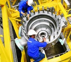
Figure 1. In a vertical design such as this one, the electric motor is mounted above the compressor, providing a very compact package. Source: Siemens.
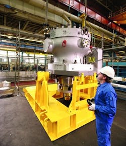
Figure 2. Flange allows lifting of the upper section with the electric motor and the compressor bundle without disconnecting the gas piping. Source: Siemens.
The design of such a compressor requires close cooperation between the compressor manufacturer and the electric motor maker. In some cases, the electric motor and compressor are connected via a conventional metallic flexible coupling to ease design, operation and maintenance. This could be a reliable high-torsional-stiffness coupling with a service factor usually above “4.” The flexible connection of the two shafts provides some essential freedom in the design of the compressor and the driver. An alternative is a common shaft for both the electric motor and compressor; vendors that can produce both a high-tech compressor and an advanced electric motor offer this configuration. Variable-speed (high-speed) electric motors in standard ratings usually are employed. The motor nominal speed frequently varies according to the compressor size. As a rough indication, smaller packages (e.g., those below 8 MW) often rely on motors with speeds up to around 20,000 rpm. Speeds from 6,000 to 11,000 rpm typically are used for above-8-MW units. These electric motors usually can be operated between 60% and 105% (sometimes, 70% to 105%) of their nominal speed.THE LURE OF MAGNETIC BEARINGSThe magnetic bearing market is fast growing; many vendors have entered the market during the last 30 years. One well-known manufacturer states that more than 800 turbo-machines with its magnetic bearings are in operation all over the world.The bearings significantly impact a compressor’s rotordynamics, vibration behavior, overall performance and reliability. So, the choice of bearings demands care. Designs that place the magnetic bearings outboard of the compressor result in an excessively long shaft (a long bearing-span) and the need for a seal. A better approach is to have the magnetic bearings inside the compressor. This can eliminate the seals and also could shorten the shaft. Plus, no lubricant is present to contaminate the compressed gas. Sensors monitor the position of the shaft and supply the position data to a digital controller. In turn, the controller can change the current in the coils of the magnetic bearing to correct the shaft position. These changes happen very quickly, allowing the position of the shaft to be precisely maintained at very high rotational speeds. With the rotating shaft suspended, there’s no metal-to-metal contact.The initial cost of the magnetic bearing system could be an order-of-magnitude higher than that of conventional lubricated bearings. Most of this cost difference is because of the relatively sophisticated control system required for the magnetic bearings. The hardware associated with a magnetic bearing system is relatively inexpensive. For example, the cost of winding a magnetic bearing coil could be comparable to that of winding an electric motor stator of the same size. However, the control system of a magnetic bearing includes such items as an advanced digital controller, sensors to monitor the shaft position, etc. The hydrodynamic bearings and associated lubrication oil system for a traditional high-speed centrifugal compressor are complex and expensive. Their operating and maintenance costs also are high. In contrast, magnetic bearing systems lack components that wear mechanically; so, the systems require none of the mechanical maintenance associated with conventional bearing systems. Overall operating and maintenance expenses are much less.The payback on an investment in a magnetic bearing system typically is a year or even less. Considering lifetime ownership cost, a magnetic bearing system is the best choice for high-speed centrifugal compressor trains.The mean time between failures for controllers is roughly 8 to 12 years depending upon how hard the electronics have been stressed and the adequacy of cooling provided. The operator can expect to make changes in the control system of the magnetic bearing after 10 to 15 years of service. Many old magnetic-bearing systems are amenable to upgrading with the latest generation of digital control cabinets, giving them new life. Like a well-designed electric motor, magnetic bearing hardware can last 20 years or more depending upon the environment in which it operates and how fast the insulation breaks down in that environment.Magnetic bearing systems suffer significantly fewer mechanical losses than conventional bearing systems. Moreover, power consumption can be one-tenth that of a conventional bearing. So, switching to a magnetic-bearing centrifugal compressor can provide considerable energy savings. In addition, the lower energy consumption and the elimination of the seals (and associated emissions) can offer environmental advantages.Magnetic bearings represent a closed-loop system architecture. The rotor, bearings, sensors and power electronics constitute a dynamic system with properties that could be set by designing a controller with the required closed-loop stability and robustness (i.e., the ability to keep properties from changing significantly if the system differs slightly from the mathematical model). A closed-loop system can be sensitive to changes in its nominal parameters. For instance, a rotor shaft whose bending mode is actively damped by magnetic bearings can be stable depending upon the amount of damping introduced. However, the system can become unstable if the resonant frequency changes slightly, which could occur because of many factors (such as thermal effects on rotor shafts). While the closed-loop stability can be assessed by criteria such as amplification factors, some other cases and parameters (for example, the sharpness of vibration peaks near resonant frequencies) require special considerations. A magnetic-bearing control system provides constant feedback about its state. This offers great diagnostic opportunities. A good example is the check of internal clearances, particularly gaps between the shaft and the mechanical backup bearing that limits the shaft axial and radial movement. An integrated compressor measurement system could offer:• multivariable signal injection (for an injection of excitation into the shaft) to evaluate the rotordynamics response with freely selectable frequency, amplitude, phase and injection point;• continuous monitoring and analysis of system states, such as vibration, displacement, temperature, misalignment, rubbing, etc.; and• an online rotor-balancing tool.For example, it’s possible to continuously monitor bending mode frequencies as part of a preventive maintenance program and detect undesirable changes at an early stage. The magnetic bearing’s minimal maintenance requirements and built-in condition monitoring make such a bearing ideal for any chemical processing compressor application. DIFFICULT GAS CHALLENGESHermetically sealed motor-compressor units that handle a clean gas can use an internal cooling system. For some special clean-gas services, the first impeller could be designed to carry a slightly larger flow than all the others so a portion of the first-stage compressed gas can be extracted and used to cool the electric motor and magnetic bearings and then returned to the suction. The amount of cooling gas recycled mainly depends upon its composition, temperature, pressure and conditions. It roughly could range between 7% and 15% of the volume handled by the machine.However, the compressed gas at many plants contains fine solid particles, liquids, water or sometimes hydrogen sulfide (a sour gas) or other corrosive and problematic components that rule out an internal cooling system. An untreated wet, corrosive or sour gas can create deposits on the hot spots of the electric motor and magnetic bearing windings that may cause a short circuit within the electric motor and the magnetic bearings. The latest solution for wet- or dirty-gas compression applications is a canned-type magnetic bearing and an electric motor with an external cooling system. An external cooling system could offer very reliable operation given proper design and required redundancy. In very special applications where an external cooling system may not be possible or desired, an electric motor having a solid non-laminated rotor (copper components usually are eliminated) with a symmetrical dirty- or wet-gas cooling system may make sense. However, these unclean-gas cooling systems currently are in the research and development phases and should be considered with a great care. A GOOD CHOICEHermetically sealed direct-driven centrifugal compressors using magnetic bearings obviate shaft-end gas seals and lubrication oil systems, two components that need extensive periodic maintenance. Also, these new compressors are less than half the size and weight of traditional centrifugal compressors. The electric motor usually is a standard size while the compressor is tailored in size and number of impellers for each application. Commonly used designs employ two to eight impellers per casing (to assemble on a shaft) in the inline or the back-to-back configuration.Hermetically sealed direct-coupled compressors offer the following important advantages: • high expected reliability (five or more years in operation without a shutdown); • simple, lightweight and compact design (an obvious plus when there are space limitations but, regardless, a benefit that can result in a smaller enclosure and foundation); and• better overall driver efficiency, flexibility and reliability in applications, say, above 1.5 MW, thanks to the use of variable-speed electrical motors. Currently, hermetically sealed compressors are more expensive than other compressor types. However, with sufficient production volume, they could become cheaper than conventional compressors because they are inherently simpler. The cooling system is the weak point of hermetically sealed compressors. Sophisticated external cooling (rather than internal cooling using the process gas) is more suitable for most chemical processing plants. The elimination of gear units, oil systems and seals is an important advantage. Also, this compressor design offers superior rotordynamics, torsional behaviors and condition-monitoring capabilities. The long-term future of turbo-compressor technology likely lies with the innovations found in this compressor type.AMIN ALMASI is a rotating equipment consultant based in Sydney, Australia. E-mail him at [email protected].
About the Author
Amin Almasi
rotating equipment consultant
AMIN ALMASI is a mechanical consultant based in Sydney, Australia. He specializes in mechanical equipment and offers his insight on a variety of topics including pumps, condition monitoring, reliability, as well as powder and fluid handling and water treatment.


