Process Puzzler: Hold Off on a Hydrogen Hike
THIS MONTH’S PUZZLER
We’re planning to increase the capacity of a diesel hydrotreater unit by replacing part of the recycle hydrogen currently used with fresh hydrogen from an existing 1,200-psig system. The header begins as an 18-in., schedule-80 pipe. The control valves are each fed from a line right off the header. Figure 1 (http://goo.gl/S801qN) shows what the header system looks like: the 1,600-ft line now handles a flow of 868 million standard cubic feet per day (MMSCFD) of hydrogen; the expansion will raise the total flow to 918 MMSCFD. One branch delivers 5 MMSCFD to isomerization. Another branch services a variety of hydrotreaters. It runs 2,500 ft and furnishes 200 MMSCFD to a hydrocracker, and then goes 3,100 ft where a common branch feeds two diesel hydrotreaters, which get 75 MMSCFD and 63 MMSCFD, respectively, and an ultra-low-sulfur diesel (ULSD) hydrotreater, which is fed 75 MMSCFD. After the diesel header, the line decreases in size to 12 in. and goes 2,700 ft to a kerosene hydrotreater fed 85 MMSCFD. It then continues 2,600 ft to a naphtha hydrotreater that gets 75 MMSCFD and to another header that delivers 140 MMSCFD to a gasoline hydrotreater and 150 MMSCFD to a fluid catalytic cracker (FCC) hydrotreater. The expansion will increase the hydrogen flow to the diesel hydrotreater 2 to 113 MMSCFD from 63; the % open for the control valve only will increase to 76% from 61%, so the project has been approved. The flows are all nominal-high values. A production engineer now is questioning the idea of increasing the fresh H2 output; he’s afraid it will put a strain on the system. What do you think?
LOOK AT THE BIG PICTURE
Anytime you increase the system demand by 50 MMSCFD, i.e., 6%, with a pressure control valve (PCV) already at 72%, there will be trouble. Obviously, the compressor supplying the H2 and the control valve are sized together. With higher flow, head will decrease eventually. The rise to 79% open for the PCV probably is caused by a drop in the compressor head.
Whenever looking at how increased loading affects a header I’ve found it best to focus on the largest demands. Although it is close to the trunk of the header, the hydrocracker, which is the greatest demand, requires a slightly higher % open from its flow control valve: 52% instead of 51%. As for the other demand on the diesel hydrotreater trunk, 76% is too high, even for an equal-% characteristic. Startup demand will be higher — and that may be more than the diesel hydrotreater 2 valve can handle.
There are a few ways out of this design trap. One may be a parallel control valve bypassing the hydrocracker — assuming the hydrogen compressor isn’t at its limit. However, this wouldn’t be cheap; you’ll need to add a new compressor house and break up the H2 system.
Replacing the control valve may not be a good option. Most globe valves, the only choice for this type of application, run 1-in. through 8-in. and then jump to 16-in. And, if your only goal is to decrease the pressure drop across the valve, you’ll face challenges in finding a valve with the right curve.
Another question to ask is why refinery management wants to add fresh H2 demand when improved water wash has been used successfully elsewhere to reduce ammonium chloride corrosion? It could be that the lower price of natural gas has them thinking of cheap H2.
Yet another question is why not attack the ammonium chloride at its source: the amine system. Amine is used to recover hydrogen from the excess added to hydrotreater reactors. Water brings the ammonium chloride with it. Why not make improvements in the amine system and improve washing in the fin-fan exchangers? These solutions will be a whole lot cheaper than making extra hydrogen.
Dirk Willard, consultant
Wooster, Ohio
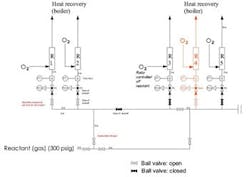
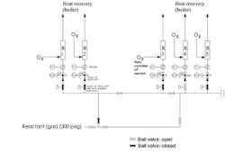
Figure 1. Operator says valve positions were as shown in Figure 1a; Figure 1b (below) shows intended design changes once new valves are installed.
JANUARY’S PUZZLER
We suffered four fatalities during the startup of a thermal oxidizer. Our superintendent blames the deaths on an operator failing to close a valve — this allowed reactant to flow to an unused reactor. Figure 1a shows the valve arrangement as described by the operator. The reactant flowed into the thermal oxidizer boiler and exploded. Figure 1b illustrates the planned arrangement of these valves. This work was supposed to be completed during the turnaround. However, the new flow meters we received were made of the wrong material; so, the changes were postponed until meters of the correct material could be shipped. The corporate safety group now is investigating. They are concerned that only valves were used for isolation but have not nailed down the cause of the accident. Do you think the operator is to blame? What do you think happened? Are the proposed design changes adequate?
Send us your comments, suggestions or solutions for this question by December 12, 2014. We’ll include as many of them as possible in the January 2015 issue and all on ChemicalProcessing.com. Send visuals — a sketch is fine. E-mail us at [email protected] or mail to Process Puzzler, Chemical Processing, 1501 E. Woodfield Rd., Suite 400N, Schaumburg, IL 60173. Fax: (630) 467-1120. Please include your name, title, location and company affiliation in the response.
And, of course, if you have a process problem you'd like to pose to our readers, send it along and we'll be pleased to consider it for publication.


