Ease Measurement of Column Internal Flow
Last month, we looked at using a gravity-flow loop to measure liquid flow inside a column (“Get Some Inside Information”). An often-attractive alternative uses a pump to return the total liquid draw taken from the column. The important engineering fundamentals of this system lie in the pump and control logic.
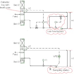
Figure 1 shows two possible configurations for measuring internal liquid flow in a column using a pump. The upper drawing represents the conventional configuration, i.e., a fixed-speed pump with a flow controller; the lower one depicts a setup with the pump controlled by a variable frequency drive (VFD). The conventional configuration may include a low-flow bypass if rates below the lower operating limit of the pump are expected. Most applications will benefit from a more-modern configuration with level controlled by a VFD.
Figure 1. Either a valve (top) or a variable frequency drive (bottom) can control the amount of liquid pumped back to the tower.
The pumped system has both advantages and disadvantages compared to a gravity-flow system.
Advantages include:
• The distance between the draw and return points isn’t critical.
• Pressure drop across the flow instrument isn’t a major issue.
• As long as sufficient pipe length for flow conditioning is available, there’s more flexibility in picking instrument locations.
• In vacuum systems, the pump supplies pressure for a sampling station (as shown in the bottom drawing in Figure 1).
• The pump also provides pressure drop for closed sampling stations, if needed.
Disadvantages include:
• The system costs more. The installation requires pump(s), foundation(s), more instrumentation and more-complex control.
• Auxiliary equipment, such as strainers, may be needed to protect the return-liquid distributor inside the tower.
• The critical distance H1 remains. It is necessary for providing sufficient net positive suction head to the pump.
•The pump and associated valves create new locations for potential leaks.
• Unit startup may be more difficult. This often is true when the draw is from a tower with trays and a full collector tray isn’t used to ensure liquid flow to the pump.
Different process requirements may favor either the pumped or the gravity-flow system. However, pumped systems tend to work more often. That’s not due to any magic. Rather, because a pump raises costs, everyone pays greater attention to system fundamentals and layout. As a result, more pumped systems get done right. However, keeping track of the fundamentals and making sure they’re applied correctly always should be a concern.
ANDREW SLOLEY is a Chemical Processing contributing editor. You can e-mail him at ASloley @putman.net

