Detailed design of a vessel includes determining the proper locations for level gauge/transmitter nozzles. There's little debate on the correct nozzle locations for vapor/liquid interface level measurements -- it's well understood to locate the upper nozzle in the vapor space and the bottom nozzle in the liquid phase. Martyn (1) discusses the challenges of liquid/liquid interface level measurements when using bridled (externally mounted) configurations. Our experience indicates that much confusion exists about the correct nozzle configurations for level measurements of liquid/liquid interfaces. Common questions include: "How do we know that the interface level in the gauge will be the same as the vessel?" and "Won't the light liquid get trapped on top of the heavy liquid in the gauge?"
So, here, we'll provide a simple "Golden Rule" for nozzle placement that we have used successfully in numerous refinery interface measurement applications.
THE GOLDEN RULE FOR NOZZLE PLACEMENT
For proper location of externally mounted level-measurement nozzles, ensure that at least one nozzle is located in the top liquid phase and at least one nozzle is located in the bottom liquid phase.
If this simple stipulation is satisfied and the top and bottom fluids are immiscible and have different densities, then we can be sure, at equilibrium, that the pressure balance will equalize the interface levels in the gauge and the vessel.
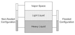
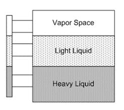
Either a non-flooded (i.e., top nozzle connected to vapor space) or flooded configuration will allow the pressure balance to equalize the interface levels in the drum and the gauge (Figure 1). The non-flooded configuration offers the advantage of allowing for a total liquid level measurement. Sometimes multiple nozzles are used to cover the expected range of liquid inventories. In these cases the Golden Rule is satisfied as long as at least one nozzle is connected to each liquid phase at all operating conditions (Figure 2).
Oil/water interfaces are common in refining, and we often hear the question: "Isn't it possible for the pressures to balance in such a way that the height of the interface in the gauge isn't the same as the height of the interface in the vessel?" A common argument is that the extra head of water in the gauge will compensate for the smaller head of oil in the gauge, thereby allowing the equilibrium interface level in the gauge and vessel to differ (Figure 3). This argument is flawed -- if the Golden Rule is followed, the two levels will equalize. The sidebar provides a simple mathematical proof by contradiction.
APPLYING THE NOZZLE PLACEMENT RULE
In practice it can be difficult to locate nozzles to satisfy the Golden Rule under all operating conditions. If a vessel may contain widely varying levels of liquid inventories, then it's worth considering multiple nozzle locations. Select nozzle positioning and spacing to minimize the chance that one no longer is connected to a liquid phase. It's possible for light liquid to become trapped in the gauge, causing an error when the light liquid inventory no longer is connected to a nozzle (Figure 3). This could occur, for example, when the heavy liquid level drops and too large a nozzle spacing was used.
Considerations other than nozzle locations can affect the accuracy of the level measurement. It's well known that temperature differences between the fluid in the gauge and the vessel can lead to erroneous readings.
AVOID NOZZLE PLACEMENT ERRORS
Adhering to our simple Golden Rule will ensure the liquid/liquid interface in the gauge matches the interface level in the vessel. If you can't manage liquid inventories to satisfy the rule then errors may arise in the measurement.
TEST THE NOZZLE PLACEMENT RULE
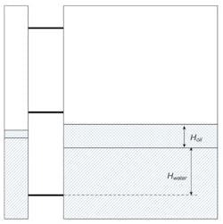
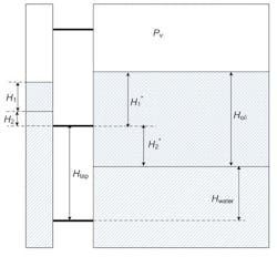
Figure 4. If Golden Rule isn’t satisfied, equalization shown isn’t possible.
In Figure 4 assume the Golden Rule is satisfied -- i.e., each liquid phase in the vessel is connected to the gauge by a nozzle. At equilibrium the pressures at the middle and bottom nozzles are balanced via Eqs.1 and 2, respectively:.>Pv + ρoil g H1 + ρwater g H2 = Pv + ρoil g H1* (1)
Pv + ρoil g H1 + ρwater g (H2 + Htap) = Pv + ρoil g ( H1* + H2*) + ρwater g Hwater (2)
where Pv is the vessel vapor pressure, ρoil is the oil density, ρwater is the water density, and g is gravitational acceleration. Substitution and algebraic rearrangement yields:
ρoil H2* = ρwater H2* (3)
Because the densities of the oil and water phases aren’t equal and H2*≠ 0 (remember we assumed that the Golden Rule is satisfied), then Equation 3 is a contradiction and can’t be true. Therefore, the equalization shown in Figure 4 isn’t possible. You can examine different equalizations, all of which will result in contradictions unless the gauge interface and vessel interface levels are equal.
JONATHAN WEBBER is a process engineer for Fluor Canada, Saint John, NB. PATRICK RICHARDS is an independent instrumentation consultant at Irving Oil, Saint John, NB. E-mail them at [email protected] and [email protected].
REFERENCE
1. Martyn, K., "Level Measurement in Bridles," Process West, p. 50, April 2006.
