In almost all solids processing operations there comes a time when the engineer must deal with a slurry (a mixture of solids and liquids). This can be in a reactor, crystallizer, centrifuge feed tank, or a pipeline. Often slurries can be treated as just another dense liquid, especially when residence time isnt a concern or horsepower issues have been addressed. What sets a slurry apart from normal liquids is a longer list of physical attributes, including: particle size, distribution, and particle shapes, with the resulting shear, settling, and drag of the particles. Most of the major problems encountered with slurries are due to a poor understanding of these factors, or from poorly obtained slurry experimental data. However, much of the knowledge obtained from pneumatic conveyors and fluidization systems can be used in understanding slurries.
Some of the properties of the liquid become more complicated once it becomes part of a slurry. Viscosity is especially difficult to determine, due to the range of solids concentrations or changes in particle size distribution that can be encountered in normal plant operations. Just as in pneumatic conveyors, the solids can build up in concentration or size along a pipeline or in a tank. Experimental work obtained under laboratory conditions wont be of much use unless it is obtained over a wide range of conditions and with scaleable tests. Even the type of viscometer used during the test influences measurements.
As an example, obtaining viscosity data requires consideration for particles bridging the gaps in testing equipment. Using viscosity instruments that test a wide range of disk or cone geometries and sizes can eliminate this problem. Particle size and particle attrition can be the primary concern for handling slurries. This may be a lesser problem than in pneumatic conveyors that use gas because of the lower velocities, but it can alter the product or lessen equipment life due to the higher shear rate of the liquid. Attrition products, due to their high surface energy, also may cause excessive build-up on pipe walls, requiring frequent cleaning of the pipes and vessels. Another complication in handling slurries is the reactivity between the solids and the liquid.
While many of the experiences and design rules of solids suspended in air can be applied to slurries, reactivity can lead to scale formation, secondary products of reaction, and agglomeration. This problem is noticeable in a crystallizer. New particles form from a reaction or because of nucleation. Unfortunately, there may be nuclei formed from attrition of larger particles. Newly formed particles tend to be extremely surface-reactive and the source of operational problems, such as scale. Excessive nuclei hinder growth or can cause products of a different morphology to be formed. The principles of good slurry pipeline design, suspension, and handling have been well defined since the early 1950s.
However there have been significant refinements to detailed hydraulic design. In most cases the strategy is to make a settling slurry into a non-settling slurry so that it can be treated as a normal, homogeneous fluid. Settling slurries are more complex, and rely on determination of the settling rate, at least for pipeline design. Several design methods are described in References 1-5 and in some proprietary publications such as Ref. 6. Some authors suggest that there are slurries that cant be effectively pumped or suspended because they cant be classified as settling or non-settling slurries [7]. For these, you must rely entirely on previous experience. This article focuses on the basic principles of suspension for solids in vessels and pipes, with an emphasis on practical rather than theoretical considerations.
Vessel considerations
Maintaining a uniform suspension in a crystallizer or a slurry tank is impossible, no matter what the theory will tell you. Although colloids and very fine particles can be suspended with appropriate agitation, only a portion of the large particles will be suspended. Agitators should be selected to provide enough suspension to keep most of the solids off the bottom of the vessel. This is very important when the solids are cohesive. In addition to agitator selection, you must consider tank design, baffle selection, and slurry takeoff points. Many solids can tolerate incomplete suspension with solids accumulating on the bottom of the vessel, but this isnt good design practice. This is especially true with bottom drain tanks where the outlet can become plugged. Although the solids can be kept off the bottom of the vessel by maintaining a minimum agitator speed, they can accumulate in the bottom drain and nozzles of the vessel. Any design should assume that and provide for back-flushing of the nozzle or dilution of the slurry by having a side port where liquid from the top of the tank can be injected into the nozzle. Specialized valves can minimize the buildup in the nozzle, but arent foolproof.
The most common method for estimating this minimum suspension condition is Zwieterings formula for the minimum agitator speed, N [8]:
N = S dp0.2 µ10.1 (g Δρ)0.45 B 0.13 / ρ10.55 D0.85 (1)
where:
S = Dimensionless parameter from agitator type, and agitator/tank diameter ratio;
dp = Particle diameter, m;
µ1 = Liquid viscosity, Pa-S;
Δρ = Difference in solids and liquid density, kg/m3;
g = gravitational constant, m/s2;
B = Weight of solids to weight of liquid, %;
ρ1 = Liquid density, kg/m3; and
D = Agitator diameter, m.
A minimum speed doesnt guarantee that solids wont be resting on the bottom. Zwieterings equation assures that settling will be limited to 1-2 seconds of contact. Also, satisfying this condition doesnt mean that solids are uniformly distributed in the tank. Even low concentrations of solids cannot be considered well mixed. If fact, low concentrations of solids often present the greatest problems in turbulent flow due to the formation of clusters or pockets of solids near the bottom of the vessel.
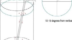
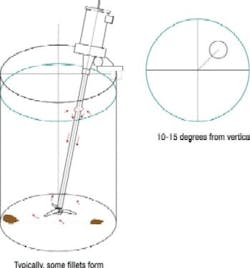
Tank shape and design details are integral parts of the agitator design. Dished bottoms and baffles help prevent settling in cylindrical tanks. Baffles impart a high vertical component of velocity, help eliminate dead zones, and can allow high agitator speeds before aeration occurs. If baffles are undesirable due to slime build-up or heterogeneous reactions, the agitator should be offset and mounted on an angle to reduce swirl and increase vertical motion (Figure 1: 10 degrees -15 degrees from vertical + offset).
Figure 1. Sometimes baffles are a cleaning problem but orientation of the agitator is crucial for good mixing.
Another option is the use of rectangular tanks since the corners provide baffling, especially for these higher viscosity systems. Agitators and impellers arent multi-purpose: choices must be made. While an impeller can handle a variety of services its functionality isnt limitless. The selection of an agitator requires a balance in power consumption, vendor claims, suspension efficiency, attrition (especially in crystallizers), number needed and type of agitator.
The most common impellers for slurries are marine propellers, 4-bladed/45° pitched turbines, and hydrofoils (usually proprietary designs). Two or more impellers may be required, either on separate shafts or on the same shaft, to provide suspension of solids, as well as mixing or blending of the tank. These impellers may, or may not, be of the same type. Often a choice has to be made between the blending or suspending the slurry, while preserving the desired reaction or products in the vessel. A variety of design procedures have been proposed for specifying impeller diameter and shaft speed for a specific duty. One that is widely available is cited in Reference 9.
An additional consideration for slurry systems is re-starting agitation after a power failure. Agitators are often unable to re-suspend the solids once they have settled. Most pumps are designed for light slurry loads and cant handle the settled solids, usually due to the high viscosity. Sparging with a liquid is the best solution for agitation. Liquid jets can recover the solids suspension, provided the solids arent extremely cohesive. Nozzles should have the capability of either back flow or solids-free liquid injection after power failures. Pumping should be stopped until the suspension is restored unless the pump is designed for such a duty. Positive displacement pumps can handle very high solids concentrations (maybe as high as 95%), but add considerable cost to the project.
Measurement of Slurry Properties
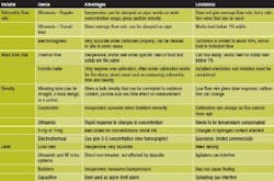
Measurement of slurry properties and process conditions is often much more difficult than with liquids and gases. However, instrumentation advances have made slurry measurements more reliable, primarily due to non-intrusive and/or non-restrictive sensors, and the durability of these devices. Examples of some selected instruments are given below: (Click to enlarge.)
A much more comprehensive analysis of these specific instruments can be found in reference 11, which has several other references to selection documents for viscometers and many other devices for process operations involving slurries.
Installation of slurry instrumentation is a little more complex than for liquids and requires a little more consideration during design. Major points are:
- Proper orientation of an intrusive sensor in the flow to compensate for erosive effects, any entrained gases, and flow conditions (laminar or turbulent);
- The effect of flow disturbances on the uniformity of the slurry and erosion;
- Providing a design that allows for bypass of the instrument;
- Providing a way to calibrate the instrument in the field, and on the actual slurry under process conditions; and
- Determining what effect long-term buildup of deposits will have on performance, and providing for sampling or audits of the process.
Transport lines
Not maintaining a suspension in a transport line can really ruin your day. While a slurry can sometimes be treated as dense and highly viscous liquid, the particle size and distribution create additional problems. Using a larger diameter line to lower pressure drop will cause settling of the solids and slug flow. This leads to higher pressure drop, abrasion, and excessive mechanical stress on the pipeline. In addition, slime may form on the interior of the pipe. And, abrasion can reduce wall roughness over time.
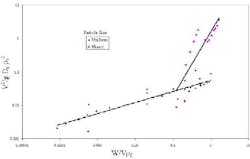
The easiest way to design a pipeline is to maintain non-settling conditions, similar to the design of dilute-phase pneumatic conveyors. As with pneumatic conveyors, operating too close to the saltation velocity can be problematic, and once a minimum velocity has been calculated, a safety factor of at least 25% should be applied. The saltation velocity is determined through an empirical relationship based on the solids loading, particle size, and physical properties of the system. Practical experience and experimental work are preferable to any theoretical model. One method to estimate saltation is shown in Figure 2 [10] and represented by Equation 2.
Figure 2. Empirical Correlation of Saturation Carrying Capacity in Horizontal Lines (10). (Click to enlarge.)
While the saltation velocity for the largest particle in the suspension is usually used, particle size distribution may be more important. For instance, a slurry with a large percentage of very fine particles may behave as a single larger particle and overshadow the effect of a few large particles. The fine particles may cluster and cause the larger particles to settle at an even higher rate, which would require a higher slurry velocity. One method to overcome this design problem is to calculate the loading of each particle size, determine the average particle size of the settling mixture, and then use it to determine the effective saltation velocity.
By using the loading that can be carried by each particle size to establish the particle size distribution of the suspension, the average particle size of the suspension give a more realistic picture of viscometric and drag forces. In this analysis, the designer must account for the piping layout to minimize settling of the solids since this will change the local solids concentration (usually increase it). Best practice dictates longer pipe runs with the minimum of elbows to prevent settling from acceleration losses at the elbows.
Determining the largest particle in the slurry can be tricky, but practical experience suggests that the particle size representing the upper 10% of the total mass in large particles works best. The exception is for particles not well distributed, or with a range of sizes covering over two orders-of-magnitude. In these cases we have to rely completely on past experience. The finer particles will agglomerate in the wake of the larger particles and hydraulically act as even larger particles (i.e., the small particles carry the larger particles).
The two distinct lines in Figure 2 are for uniform and mixed particle size solids. The wider the distribution, the quicker the correlation deviates from a straight line (when W/Vρf > 0.1). If the particle size varies by only 3 to 4 fold, the following equation, which is valid for uniform particle size, can be used until W/Vρf > 10:
V2/g Dp ρp2 = 0.0556 (W/V ρf)0.33 (2)
where:
V = Superficial fluid velocity at the saltation point, ft/s;
Dp = Particle diameter, ft;
ρp = Particle density, lb/ft3;
ρf = Fluid density, lb/ft3;
W = Solids mass flow rate at the saltation point, lb/s/ft2; and
g = 32.2 ft/s2.
Defining suspension requirements
Some questions to ask regarding particle suspension are:
- Where is this slurry going? If a filter or centrifuge will be next, it will be important to maintain the slurry integrity. If a dryer follows one of those, this may be less of a concern; the solids could be re-mixed in the dryer. However, operational problems can result in the filter or centrifuge due to settling of the solids. Not maintaining enough motion of the solids can cause problems with the feed to centrifuges or downstream reactors. One very common complaint when feeding batch centrifuges or filters is the variability of the slurry feed particle size. When the feed tank is full, the centrifuge or filter receives mostly large sized particles and the filtration rate is very good. As the tank empties the particle size becomes smaller, the filtration rate is slower, and cake quality becomes poorer. Eventually, the centrifuge or filter may plug. The root cause of the problem is often over-sizing of the feed tank (either too large or too tall for the agitator height). One easy fix when this problem is encountered is to recirculate the feed to the centrifuge or filter back to the feed tank so that flow back to the tank is maintained at all times.
- How variable is the particle size distribution? Many designs are based on the largest particles and fail to account for particle distribution. Fine particles can get into the boundary layer of the flow, increasing the shear rate and overall pressure drop. Particles also may settle in the boundary layer and sluff off, disrupting the laminar layer or turning laminar flow into turbulent flow. While the resulting pressure drop may decrease, the return of laminar flow may cause solids to separate and become a slugging or erratic flow. This may turn a non-settling slurry into a settling slurry, where different design rules apply. Large concentrations of fine particles also can turn a normal non-settling slurry into a settling slurry due to hindered settling effects. The lower drag from local turbulence causes fine particles to cluster and act as a much larger particle.
- What are the consequences of poor suspension? Most crystallizers will still make an acceptable product even without fully suspended solids. Attempts to mix the suspension further may not be desirable due to attrition or power consumption. It may be more inexpensive to install several re-suspension points on a long pipeline rather than take the chance that a change in the particle size distribution may cause a problem. Can fluid injection along the line or in a vessel return a plugged system to operational? If so, it may be more inexpensive to plan for blockages than to try to design around them. When faced with a new system or a large scale-up situation, this may be the best course of action.
- What experimental data are needed for design? If you dont have an existing slurry system to draw from, the design will be developed from physical property data and hydraulic models. It will be important to determine the settling characteristics of the slurry and determine to what extent it can be treated as a non-settling slurry. These data are needed in addition to the physical properties and the rheology (Newtonian, shear-thinning, shear-thickening, or Bingham plastic) of the slurry. More effort must go into defining the viscosity, particle size, and variability of the slurry than in scaling up an existing system. However, scale-up of an existing system must insure that settling of the slurry is properly handled, such as accounting for the effect of larger diameter pipe on saltation.
- How will the system (pipeline, agitation, etc.) be controlled? While not a focus of this article, there have been many improvements in on-line instrumentation for slurries (see sidebar); these should be a major part of the design. Many chemical plants lack adequate instruments for solids or slurry flow because these were expensive, unreliable, and the need wasnt well understood many years ago. Slurry density can be controlled more precisely and blockages eliminated through simple non-intrusive flow meters or velocity sensors. At a minimum, sample ports must be provided to allow for determination of slurry characteristics after the design is installed. The experimental work should have identified and incorporated some key process variables (shear rate, density, and particle size) into the overall control strategy.
Succeed with slurries
Designing reliable slurry-handling systems starts with an understanding of the slurry properties, especially settling rates, viscosity and density. It is rare that physical properties can be obtained from empirical correlation or existing databases, as may be the case for single-phase liquid mixtures; testing is required before design. Even scale-up from an existing installation may be difficult due to the variability of settling characteristics. However, an existing installation is often a better source for design than a theoretical design using standard viscometric design methods.
With the correct attention to obtaining the physical properties, consideration of adequate instruments, and an understanding of the principles of slurry design, there is little reason that operators should have problems handling slurries.
References:
- Brown, N.P. and N.I. Heywood, eds. Slurry Handling: Design of Solid-Liquid Systems, Kluwer Publications, Dordrecht, The Netherlands (1991).
- Govier, G.W. and K. Aziz, The Flow of Complex Mixtures in Pipes, Van Nostrand Reinhold (1972).
- Heywood, N.I., Pipeline Design, Slurry Systems, in Encyclopedia of Chemical Processing and Design, 36, pp. 363-399, Marcel Dekker, New York (1991).
- Heywood, N.I., Stop Your Slurries from Stirring Up Trouble, CEP, pp. 21-41, (September, 1999).
- Worster, R.C. and D.F. Denny, Transport of Solids in Pipes, Proc. I. Mech. E., 169, pp. 463-486 (1955).
- Allsford, K.V. and N.I. Heywood, Pipeline Design for Slurries and Pastes, State-of-the-art Review, Wet Solids Handling Report 6, AEA Technology, Oxford, U.K. (1985).
- Cheng, D.C.-H. and W. Whittaker, Paper C2, Hydrotransport 2 (1972).
- Zwietering, T.N., Suspending of Solids in Liquids by Agitators, Chem. Eng. Sci., 8, pp. 244-253 (1958).
- Gates, L.E. et al., Selecting and Agitator to Suspend Solids in Liquids, Chem. Eng., pp 144-150 (May, 1976).
- Zenz, F.A. and D.F. Othmer, Fluidization and Fluid-Particle Systems, Figure 10.9, Reinhold Chemical Engineering Series, p. 328 Van Nostrand Reinhold, New York (1960).
- Brown, N.P. and N.I. Heywood, The Right Instrumentation for Slurries, Chem. Eng., pp 106-113 (September, 1992).
Thomas R. Blackwood is director of technology forHealthsite Associates, Ballwin, Mo.; E-mail him at [email protected]. He also serves as the solids processing guru in the Ask the Experts.
