August Process Puzzler: Remove operating problems not just an impurity
Question from June's Chemical Processing
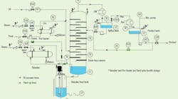
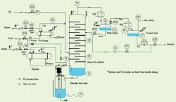
Our fractionating column is notorious for its problems. Oil is injected into heated feed to separate an impurity. This approach eliminates the impurity well, perhaps too well. A sludge collects in the bottom of the reboiler feed tank, clogs the sieve column and plugs the reboiler and pre-heater. There’s some concern that separation efficiency is affected by plugging of the trays but the main problem is frequent fouling of the heaters, which have fixed heads and are difficult to bore out. The reboiler pump fails often and we must call in a vacuum truck frequently and unexpectedly to clean out the reboiler feed tank. Start-up is often a problem because the steam plant is far away. The oil frequently burns, which adds to our fouling woes. What can you recommend to reduce sludge build-up in the trays, heaters and reboiler feed tank?
Figure 1. Switching to steam sterilization may affect seals, bearings and pump performance. (Click to enlarge).
Install basket filters
First, fire the chemist who suggested using oil to remove impurities. Second, demote the plant manager who acceded to this nutty idea. Third, while you’re looking for a better impurity remover, install three or four basket filters (you get to pick the mesh size and the basket size), each manifolded to the “bottoms” and leading back to the reboiler feed tank.
Depending on the viscosity or flow rate telling you when the basket is starting to fill up with gunk, use an external level detector or flow meter to automate the solenoid switchover to another basket filter. Then, hire a Chinese fire drill brigade to empty, clean out and return the basket filters. (This is said tongue-in-cheek, to let you know sometimes we aren’t serious.)
Tom Murphy, CEO
Puritrol, Inc., Centerville, Mass.
Consider three options
It seems like the problem is that we’ve introduced a non-volatile component into a distillation system and that the component is collecting in the low spot of the system over time. Once it builds up enough, the pump sucks it in and then distributes it to the heat exchangers.
I would propose several solutions to this problem:
- Does the oil need to enter the fractionating system or can it be removed in the feed prior to the column? From the description, the impurity combines with the oil to create a sludge that’s denser than the feed or the bottoms product, so perhaps install an extraction system in the feed line downstream of the mixing point that could be as simple as a holding tank that allows the sludge to drop out of suspension and collect in the bottom of the tank. The tank could then be sucked out periodically as necessary to remove the impurity or, if possible, the oil could be filtered and recycled in the process. This would be capital intensive but solves the column problems, exchanger problems, pump problems, and start up problems. It also limits operator involvement if potential exposure to the process fluids is unacceptable.
- Run the reboiler feed tank at a higher level and shorten the suction line of the reboiler pump. Automate the drain or make it standard operating procedure to drain the bottoms of the reboiler tank periodically to remove the sludge from the system before it wipes out the pump and fouls the exchangers. This solution is almost capital-free but the oil still enters the column and there’s a good chance for an upset that would introduce the sludge into the heater system. During start-up you could establish levels with oil-free feed since the column is on total reflux and then introduce the oil after establishing stable bottoms levels. The drawing doesn’t show the bottoms draw on the column so it’s unclear what effect the impurity would have on this part of the column.
- Install a side-stream filter system utilizing the differential pressure across the reboiler pump that will remove over time the sludge that’s present in the column bottoms, similar to a side-stream filter in a cooling tower/jacket water line. The column will still see the full amount of the oil and the pump will see a small portion of the sludge but probably not enough to affect the reliability of the pump to a major extent. This solution requires some capital but is probably less prone to upsets than option 2. Again, during start-up you could establish levels with oil-free feed. This would potentially expose operators to process chemicals during the filter change outs, so it may not be acceptable.
Brad Piggott, engineer
Air Liquide America, Houston
Pull a vacuum
Perhaps the impurity could be removed in the fractionation column without adding the oil if the column were operated under a vacuum (or a lower vacuum if it’s under vacuum now). Depending on the chemicals involved, deeper vacuum would require lower heat input to cause the fractionation. The statement “oil frequently burns” indicates a high temperature of operation. Lower operating temperatures would help lower or eliminate that. The impurity may have a different boiling point at a lower pressure and eliminate the need to add oil to separate it.
Henry H. Hesser, staff technical specialist
Busch, Inc., Virginia Beach, Va.
What really is the problem?
You could have any one of a combination of problems. The response and possible improvements depend upon the specific problem you have. I’m assuming that the “heavy oil” goes overhead and the contaminant goes bottoms for the most part. A partial list of possibilities include:
- solids contamination;
- heavy oil with a moderate relative volatility;
- heavy oil with a low (or no) vapor fraction in the feed and reactive at tower conditions;
- heavy oil with a low (or no) vapor fraction in the feed and reactive (or reaction initiated) at reboiler conditions; and
- heavy oil with a low (or no) vapor fraction in the feed and inherently reactive with itself or other process components.
Solids contamination. Solids entering the process will go somewhere and they will go down. If you are putting solids in the process your choices are simple: remove them upstream, remove them in the process or remove them downstream. Have you considered a wiped-film evaporator on the heavy oil feed? This would eliminate the solids and send a vapor stream to the tower. Once the solids enter the tower the best you can do is keep them moving. Electropolish the trays; install fixed, directional valve trays with large openings; and make sure the tray flow patterns don’t have dead spots. This moves the solids to the tower bottoms and exchangers.
Some towers have successfully used trash collectors on a bottom tray sump or other locations to keep solids out of the reboilers and bottoms pumps, with manholes or handholes to ease cleaning. Once the solids get past the tower bottoms they’ll end up in the reboilers and bottoms pumps. At that point, you need to have bundles that are easy to clean.
From your description, it sounds like you have the tower side (process service) in the tubes. I don’t see any simple solutions to improving exchanger performance here. Polishing the tubes to prevent sticking may help but the solids still go somewhere. The soundest approach to preventing reboiler problems is probably reboiler replacement. Helical baffle and spiral-plate exchangers as well as conventional non-fixed-head exchangers may all be good choices. Reboiler pumps also lack clear solutions. Solid crusher pumps are available if your pressure and temperature are in the correct ranges. Filters installed between the tower and pump may help but be careful of pump NPSH. Once filters are installed you need to clean them as well.
Heavy oil with moderate or high relative volatility. Heavy oil with a moderate vapor fraction of the heavy oil in the feed implies that the heavy oil can go overhead easily. Moving the feed location up would increase stripping effectiveness of the heavy oil. If the problems arise from the temperature-driven kinetics of reactions of the heavy oil, moving the feed point up and the heavy oil into a cooler section of the tower may slow the reactions down, helping the tower stay clean. The vapor/liquid equilibrium needs to be checked as well as other process and equipment constraints.
Heavy oil with low (or no) vapor fraction in the feed. If the heavy oil has a low (or no vapor) fraction in the feed and is difficult to vaporize (low relative volatility) a high concentration of the oil will accumulate in the reboiler regardless of the tower feed point. Reboiler temperatures rise. This increases the rate of many fouling mechanisms and stresses machinery seals. Even so, you may be able to improve the situation.
— and impurity reactive at tower conditions. Cooling the tower and keeping the contaminants moving may be the best approaches. Running at minimum pressure may drop tower temperatures enough to slow fouling. Keeping the fouling material moving has already been discussed.
— and reactive (or reaction initiated) at reboiler conditions. More scope for improvement is possible if elevated surface temperatures in the reboiler are required to initiate fouling. Approaches may include setting the controls to minimize reboiler temperatures (steam chest operation instead of flooded tubes on the reboiler utility side); minimizing tower pressure; running the tower as a steam distillation (adding water to the system) if possible; recycling light material to the bottoms (from the product, for example); or increasing reboiler area.
— and inherently reactive with itself or other process components. This situation doesn’t leave much scope for action. Minimizing temperature may help but will not make the problem go away. The best methods here keep the contaminants completely out of the process, change the system chemistry or make equipment changes to deal with the inevitable shutdowns. Keeping the contaminants out returns to the idea of the wiped-film evaporator or other dedicated equipment. Additives can change the system chemistry. Along with equipment changes, new arrangements for easier start-up may be required.
Andrew Sloley, principal engineer
VECO USA, Inc., Bellingham, Wash.
Switch to jet trays
In the one of our towers we contracted the same problem and during one year plugged all holes of trays with hydrocarbon and hole diameters were reduced from 13 mm to 5 mm. We replaced all of the trays with jet type. Now that tower has been in service for two years and we haven’t seen increasing pressure drop or other issues.
If space is sufficient in the bottom of tower, it may make sense to install a baffle and collect sludge on one side and clean fluid to go to reboiler on the other side.
Razi Torabi, utility process engineer
Tabriz Petrochemical Co., Tabriz, Iran
Use an emulsifier
The problem with the clogging of the column parts could be solved by adding an emulsifying agent to the feed, so that it may retain some more of the components that keep it fluid at the end of the run. This emulsifying agent could be selected simply based on achieving this goal or on just modifying the surface tension of the bottoms so that they can be pumpable out of the system. There may be a drawback to this solution in that the tower may loose some of its efficiency to remove the desired distillate, as some of it will be retained with the emulsifier in the bottoms.
Luis Alejandro Betancur González, process engineer
Research on Industrial Process, Inc., Medellín, Colombia
Look at the exchangers and pre-heater
There are two classes of problems I can discern from the puzzle description: operating difficulties and maintenance issues. Of the two, the easiest to solve are those involving maintenance. Let’s consider maintenance first. The first problem is the choice in heat exchangers.
These appear to be TEMA Class BEM units, which are difficult to maintain and do not belong where steam is used. B-E-M stands for integral bonnet cover (B) with a single shell pass (E) and a fixed tube-sheet (M). As a rule of thumb, allowance should be made for thermal expansion where the temperature difference between the tube-side and shell-side fluids is greater than 70°F (39°C). This has been stretched to 100°F but it is better to err on the conservative side.
A better choice might be TEMA Classes BEP, BES or BET. It is worth noting that expansion joints should be installed on most equipment where there is a similar potential temperature differential but they could be missing due to an oversight by a lazy CAD-driver. There are other self-inflicted wounds festering in the design of this column.
If the oil is being burned and causing a clogging problem in the column it may be due to poor temperature control in the pre-heater. With the steam plant at a distance, it could be that the column is not receiving its share of saturated steam but is getting a mix of condensate. The temperature control valve on the pre-heater could then be swinging too far open and isn’t operating in its design range. An over-zealous operator running the loop in manual could have a similar detrimental effect. The venturi meter could be used as a tool if it’s reading high during start-up since it measures fluid velocity; condensate will partially block the tube. Another approach would be to do a material and energy balance around the pre-heater to determine the true enthalpy of the steam. A few process changes might eliminate the burning problem.
One approach might be to substitute the oil with another solvent that’s less temperature-sensitive. Another could be to add the oil directly to the column bottom. Mixing could be a problem, but this might be addressed by spraying or adding an in-line mixer or static mixer. Perhaps the reboiler pump could be used. The idea is to give the oil time to heat up rather than allowing it to be scalded by hot feed. A column simulation would make it easier to determine the optimum solution(s). There are a few more drastic measures for reducing fouling, at least in the column. Consider increasing the sieve size in the trays. Again, a simulation is recommended to evaluate the effect of this option on product quality.
Now, let’s look at the process problems. Clearly, the oil is doing its job. The impurity is being removed but the process is not designed to handle the quantity of solids collected in the reboiler feed tank. The evidence of a problem with solids is the way a control engineer chose to measure level in the reboiler feed tank: a nuclear level transmitter. This method is a favored choice when sludge build-up rules out most other modes.
Measuring the solid is easier than managing it. Years ago, when a similar situation came up I suggested an automated strainer; my boss went with a suction strainer. With the suction strainer, which was an integral part of the pump, the reboiler pump had to be replaced and up-sized. The automatic strainer provided some of its own pressure so it was debatable whether the reboiler pump needed to be replaced. Mechanical reliability was in doubt with the discharge strainer because of the severe corrosion.
Our choice of materials was usually Inconel 600. Neither pump solution would eliminate the need for collecting and land-filling a wet solid from the bottom of the feed tank. Unfortunately, little progress seems to have been made in automating drying technology especially in applications involving dirty or corrosive solids. My preference would be a vacuum dryer but it is only good for a maximum of 40% removal. Vacuum dryers require little operator attention, at least compared to other drying methods.
Dirk Willard, process engineer
GTP, Schaumburg, Ill.
|
October's Puzzler |
|
A spray condenser tank uses a float as a level instrument. Metal chlorides settle in the tank and are eventually pumped to waste treatment. Unfortunately, solids build up, especially during start-up, causing failure of the float. Last year alone, eight floats were replaced. Two months ago, two floats were replaced during a single outage, causing more than 30 hours of unexpected downtime. The current instrument is loop-powered. There are no additional points left in the PLC for self-powered instruments. Can you propose alternatives for measuring level? Send us your comments, suggestions or solutions for this question by September 7, 2007. We’ll include as many of them as possible in the October 2007 issue and all on CP.com. Send visuals — a sketch is fine. E-mail us at [email protected] or mail to ProcessPuzzler, Chemical Processing, 555 W. Pierce Rd., Suite 301, Itasca, IL 60143. Fax: (630) 467-1120. Please include your name, title, location and company affiliation in the response. And, of course, if you have a process problem you’d like to pose to our readers, send it along and we’ll be pleased to consider it for publication. |


