This Month’s Puzzler
Our steam stripper isn’t performing as designed. We are seeing 1,200 ppm of bottom contaminants instead of the 400-ppm expected. We anticipated foaming but it is much worse than foreseen, requiring us to cut back the tower rate. We tried raising the bottoms temperature and replaced our anti-foam pump with a larger one, increasing the addition rate.
The reduction in tower capacity, downstream purification of the bottoms and injection of anti-foam was killing our bottom line.
When we still couldn’t meet necessary production and quality, we replaced the upper half of the sieve trays with two beds of random packing, a high-performance glass-filled polyethylene type. (We couldn’t replace the sieve trays entirely because the temperature at the bottom of the tower exceeds the limit for the packing, i.e., 180°F.) We installed a distribution pan at the top of the packing and a single vapor distributor in the bottom bed.
For a week after addition of the packing, the tower almost ran within specifications and we were able to increase capacity by 50% over the initial rate. I think we solved our foaming problem with a 50% reduction in defoamer addition; now, the pump is oversized.
Did we miss a treatment step? What could the bottom contaminants be and what can we do about them?
Check Operating Parameters
Although steam stripping is a common process for wastewater (CO2, H2S, HCN, NH3, hydrocarbon stripping) and some refining operations, the problem statement is fairly general, containing little information about the application or process.
Consider:
1. Because the process worked for a short time after retrofit with packing and trays (fairly close to the specifications), it is quite possible operating upsets or abrupt process changes (e.g., striping steam flow, high level in the bottom, process flow) during startup/shutdown or control system disturbance could have damaged internals. For instance, high liquid levels cause hydraulic shock (water hammer) that could dislodge trays, distributors (steam entry and/or liquid distributor), downcomers, or packing, consequently affecting vapor/liquid contact efficiency. Review a historian or the distributed-control-system trends to identify if there were abrupt operational changes and consequent problems with bottom effluent quality going off-spec. However, to verify the damage, you may need column x-rays to help identify damaged areas or components. This will help streamline planning for a shutdown and repairs. Of course, for environmental compliance applications (e.g., wastewater effluents), you must closely coordinate shutdown with the regulatory compliance team.
2. If the process stream is heavily fouled, its carryover will foul the stripper, which could cause premature flood and, hence, poor quality of the effluent. Filters and strainers in the incoming stream would help minimize this problem.
3. Check stripping-steam quality, temperature and pressure. Extremely wet steam is not effective in a stripping process. Bad steam traps and/or mud legs will end up leaving a large amount of water in steam, rendering it ineffective for stripping. A high proportion of water also could cause water hammer, which, in turn, could damage internals.
4. Check the ratio of steam flow to process flow and compare that against the normal operating ratio. Ensure flowmeters (for steam, process flow) are working properly.
5. If you have online analyzers, examine the concentration (of the species to be stripped) to see if it has gone up. If you don’t have them, review the laboratory analyses database.
6. The statement “tower almost ran within specification” suggests a need to check the design — for example, the height equivalent of a theoretical plate of the packing, tray efficiency and operating envelope.
7. If the defoamer has been stored for a long time it may be past its shelf life.
GC Shah, consultant
Houston
It’s Always Maldistribution
Most problems with changes at least partially involve people. It’s the “pilot error” of our business. Perhaps a “new” contractor or its crew foreman was unfamiliar with your standards for installing random packing and distributors, etc. Someone senior should have inspected this job in detail. Making any operator solely responsible for equipment, without maintenance approval, is a dumb way to run an operation.
As for the technical issues, the most common problem with packing is maldistribution. Look at the liquid distributor on top. Also, verify the packing type; it’s common to assume that one packing is the same as the other — but not, I assure you, to the design engineer. Re-evaluate the use of one vapor distributor. My experience is that you get best results by installing a vapor distributor every 15 ft of packing of a new bed; that’s a good rule of thumb.
Don’t just assume the process upstream and downstream are stable. Spend a day listing any changes that occurred there, regardless of whether they affected your process. Never rule anything out until you have to do so!
Here’re a few questions:
1. How was packing supposed to reduce foaming?
2. How close to the packing’s temperature limit are you? Packing can melt from even temporary excursions, causing poor performance and, perhaps, increased foaming.
3. Is something wrong with the liquid distributor? Is it tilted? Is it sealed to the vessel shell? Is the feed to the distributor affecting even flow to the packing below?
4. When you installed the packing, did you pass it through a strainer? Glass-filled packing is less of a problem with fines because manufacturers generally remove the dust. However, this may not be true with all manufacturers and other materials, like ceramics.
5. Is the contamination target really the only quality control measure you’re using? How do you know if contamination isn’t part of the upstream process or created by reaction in your distillation column?
Dirk Willard, consultant
Wooster, Ohio
March’s Puzzler
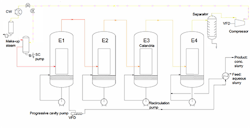
Figure 1. Contamination and corrosion afflict the operation.
Our evaporation train was running perfectly. Then, the internals suffered corrosion and corporate engineering decided to replace the type-304 stainless-steel calandria with one made of type-316L. They also expanded the capacity of the system and installed a radial-flow recompression compressor in the last evaporator of the four-evaporator unit (see Figure 1). The compressor recovers steam, which is blended with make-up.
That’s when our nightmare began. Solids contaminate steam captured by the compressor. The separator appears to be undersized. After only two years, we are seeing stress corrosion cracking (SCC) in the calandria and even in the shaft and impeller of the compressor.
I’m wondering if we should dig deeper, perhaps look at the steam composition. One engineer suggested treating the steel in the calandria to protect it. Another suspects chlorine SCC but can’t find the source; he says we should replace the whole evaporation system with one made of a nickel alloy. An inspection of the compressor seal oil pump reservoir found burnt product, rust and water. A compressor expert corporate hired wants to improve the separation. Any ideas? I’m out of options. Without the recompression compressor, we push our boilers to the limit in running this evaporation train.
Send us your comments, suggestions or solutions for this question by February 11, 2022. We’ll include as many of them as possible in the March 2022 issue and all on ChemicalProcessing.com. Send visuals — a sketch is fine. E-mail us at [email protected] or mail to Process Puzzler, Chemical Processing, 1501 E. Woodfield Rd., Suite 400N, Schaumburg, IL 60173. Fax: (630) 467-1120. Please include your name, title, location and company affiliation in the response.
And, of course, if you have a process problem you’d like to pose to our readers, send it along and we’ll be pleased to consider it for publication.


